UTAustinX: UT.RTBN.12.01x Real-Time Bluetooth Networks - Shape the World
Index
1. Introduction to RTOS
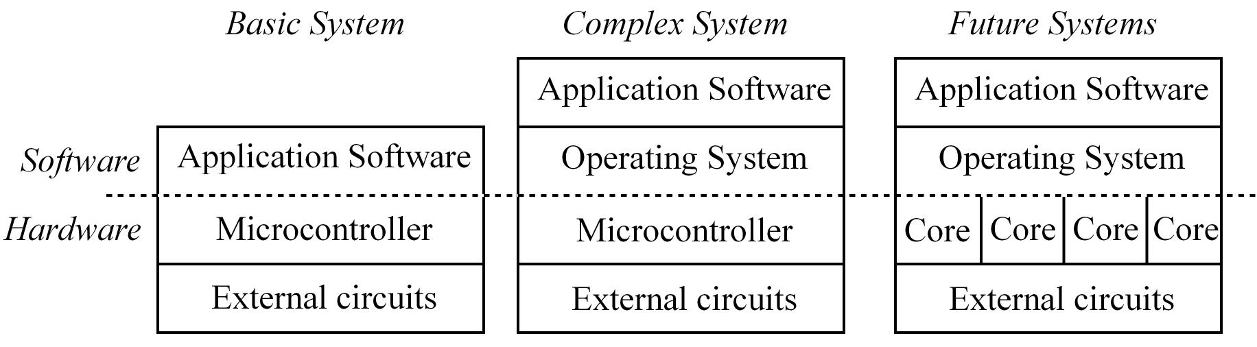
A Real-Time Operating System (RTOS) is software that manages a computer system resources (memory, I/O, data, processor time, etc.)
like a traditional OS and besides it guarantees all timing constraints are satisfied. Main characteristics of an RTOS:
- Manage resources
- Guarantee strict timing constraints, guarantees response in a defined time (deadline), this means timing must be deterministic
- Provides predictable and reliable operation
- Support synchronization and communication between tasks
RTOS have very specific metrics so considering the peak performance that need to be handled is essential
latency is the difference between the time a task is scheduled to run, and the time when the task is actually run
Real-time means the system guarantees that important tasks get run at the correct time and also are completed at the right time
ARM Cortex-M processor Considerations for RTOS
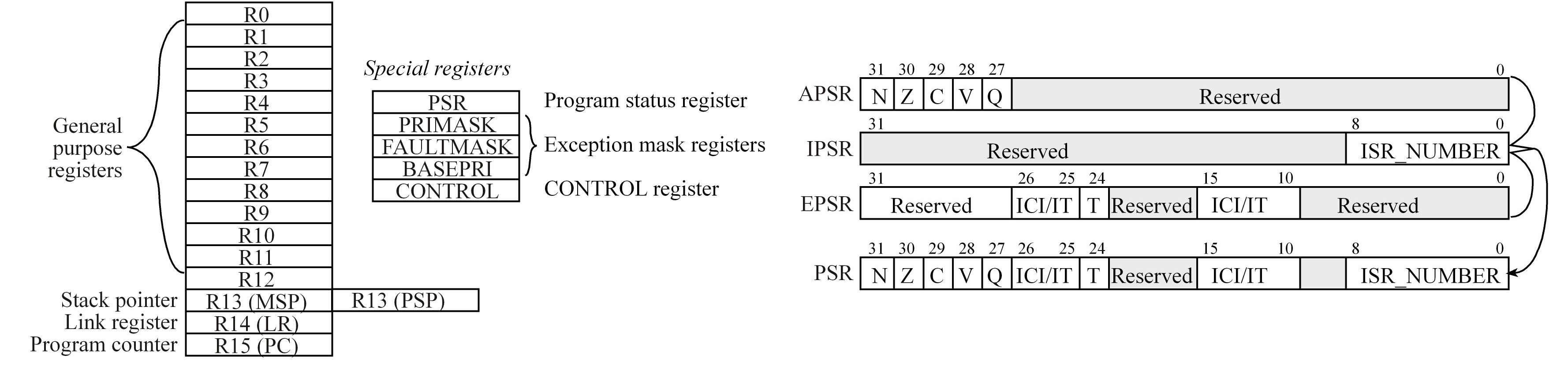
The T bit in the PSR registers will always be 1, indicating the ARM Cortex-M processor is executing Thumb instructions.
The ARM Architecture Procedure Call Standard (AAPCS) part of the ARM Application Binary Interface (ABI), uses registers
R0, R1, R2, and R3 to pass input parameters into a C function or an assembly subroutine and place the return parameter in Register R0
R4-R11 contents must be preserved so if these registers are needed during a subroutine the function must save R4-R11, use R4-R11, and then restore R4-R11,
Making sure we push and pop an even number of registers to maintain an 8-byte alignment on the stack.
ARM Architecture Procedure Call Standard (AAPCS) is used to properly connect C and Assembly languages
ARM's Cortex Microcontroller Software Interface Standard (CMSIS) is a standardized hardware abstraction layer for the Cortex-M processor, allows the standardization of I/O functions
The Software abstraction for the I/O layer is what is commonly known as the hardware abstraction layer (HAL), device driver, or board support package (BSP).
The Stack
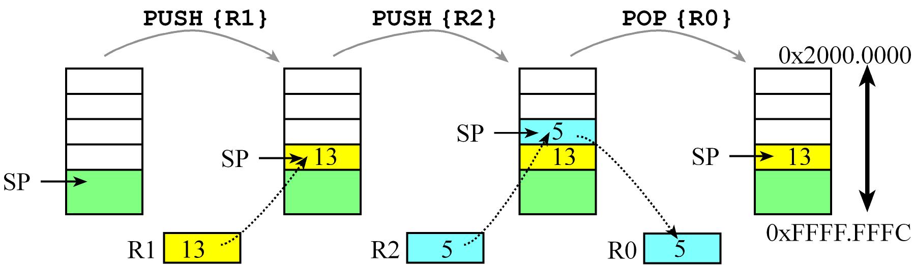
The stack is just a region of memory in the RAM, managed as a Last-In First-Out (LIFO) data structure by the stack pointer
which initially points to the bottom of that region, the stack grows to lower addresses so the stack pointer always points
to the top of the stack which means it points to the last inserted element or newest pushed element (this item is actually the stored at the lowest address!)
PUSH Operations decrement the Stack pointer SP and then store 32-bit data at the SPPOP Operations first retrieve 32-bit data then increment the Stack pointer SP
ARM Cortex-M processor has two stack pointers: the main stack pointer (MSP) and the process stack pointer (PSP).
Only one stack pointer is active at a time.
In a high-reliability operating system, we could activate the PSP for user software running at an unprivileged level and
the MSP for operating system software running at the privileged level. This way the user program could crash without disturbing the operating system
Stack Guidelines
- Balancing the stack means making sure we have equal number of pushes and pops
- if you push more data on the stack than you pop it, then that could cause a stack overflow
- if you pop more data on the stack than you push it, then that could cause a stack underflow
Perform push/pop operations only in the allocated area and don't violate the linear growth of the stack
which means DO NOT read or write to the region in the stack using other mechanisms besides PUSH/POP operations
Perform aligned operations this means PUSH/POP must be 32-bits operations so least significant two bits of SP must always be 0.
Reset and Operating modes
TMC4123 I/O
An interface is defined as the collection of the I/O port, external electronics, physical devices, and the software,
which combine to allow the computer to communicate with the external world. An example of an input interface is a switch
In a system with memory-mapped I/O, the I/O ports are connected to the processor in a manner similar to memory.
I/O ports are assigned addresses, and the software accesses I/O using reads and writes to the specific I/O addresses.
These addresses appear like regular memory addresses, except accessing them results in manipulation of a functionality of the mapped I/O port,
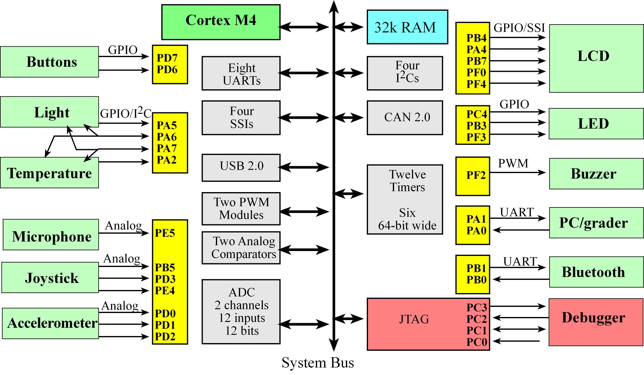
- Usual speed categories for I/O on a RTOS
- Fast, on the order of 1 to 100us: switches, LED, and microphone
- Medium, on the order of 1 to 10ms: joystick and buzzer
- Slow, on the order of 1s: light and temperature
ARM Cortex-M Essential Assembly
- The 12 essential instructions are:
LDR STR MOV PUSH POP B BL BX ADD SUB CPSID and CPSIE
- There are also pseudo-ops that the assembler uses to control features of the assembly process. pseudo-ops are basically a combination of other assembly instructions, pseudo-ops examples:
AREA EQU IMPORT EXPORT and ALIGN
- Thumb-2 instructions can be 16 or 32 bits wide
- we use the
BL instruction to call a subroutine. At run time, the BL instruction will save the return address in the LR so the last instruction in a subroutine will be BX LR, which we use to return from the subroutine.
- The listing is a text file containing a mixture of the object code generated by the assembler together with our original source code.
- The addressing mode is the format the instruction uses to specify the memory location to read or write data. Basically it specifies how the instruction accesses data.
| Addressing Modes |
Description |
Example |
| No addressing mode |
Instructions operate completely within the processor and require no memory data fetches |
ADD R1,R2,R3 |
| Immediate |
Data within the instruction |
MOV R0,#1 |
| Indexed |
Data pointed to by register |
LDR R0,[R1] |
| Indexed with offset |
Data pointed to by register plus offset |
LDR R0,[R1,#4] |
| PC-relative |
Location is offset relative to PC |
BL Incr |
| Register-list |
List of registers |
PUSH {R4,LR} |
Profiling
Profiling is a type of performance debugging that collects the time history of program execution. Profiling measures
where and when our software executes.
With profiling we can determine both a time profile (when) and an execution profile (where) of the software execution.
2. Thread Management
Threads
A program is a sequence of software commands connected together to affect a desired outcome, they are static and lifeless entities.
A thread is a piece of software (program) in it's state of execution.
A thread is defined as either execution itself or the action caused by the execution. A threads is a program in action, they are dynamic
- The thread state is captured by the current contents of the registers and the local variables
- Threads are also known or called light-weight process.
Threads abstracted by an OS or RTOS should look like each have a separate stack, its local variables are private,
which means it alone has access to its own local variables but in reality there is just one set of registers that is switched
between the threads as the thread scheduler operates, they do share resources such as global memory, and I/O devices
The thread switcher will
- Suspend one thread by pushing all the registers on its stack
- Saving the SP
- Changing the SP to point to the stack of the next thread to run
- Then pulling all the registers off the new stack.
Threads categories:
- Periodic Execute periodically, every specified amount of time
- Aperiodic Execute usually due to events E.g. user pushed a button
- Sporadic They are exception to the function of the system, Execute due to exceptions in the system
Types of threads in simple RTOS
- Event Threads or Trigger Threads: Attached to hardware and should execute changes in hardware status, like responding to an input trigger, outputting data or timer trigger. The time to execute an event thread should be short and bounded, they execute and return
- Main Threads: execute like main programs that usually never return (run indefinitely)
A producer thread is one that creates or produces data
A consumer thread is a thread that consumes (and removes) data
TCB (Thread Control Block) is a common name for a data structure to implement an RTOS thread which holds the attributes of a thread.
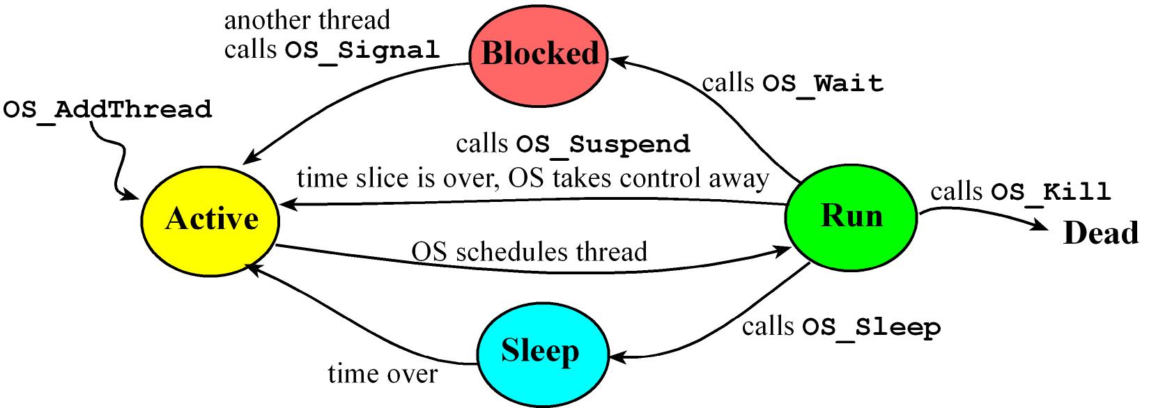
Threads States:
Active Thread is ready to run but waiting for its turn
Run Thread is currently executing
- While running a thread can spin which means a thread is waiting on an event. A thread that is spinning remains in the active state, and wastes its entire time slice checking the condition over and over
Sleep Waiting for an amount of time after which the OS will make the thread active again
- When a thread needs to wait for a prescribed amount of time, it will sleep, meaning it will not run until the elapsed wait time has passed
Blocked waiting for an event or something else, could be it's waiting for some external event like input/output
- when a thread is waiting because it cannot make progress it will block
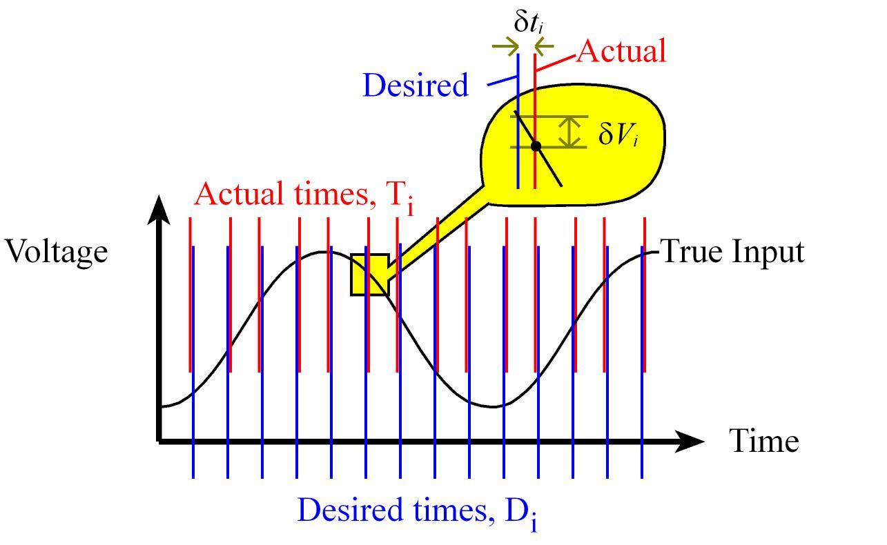
Latency and Jitter timing constraints
Latency (Δi) refers to the time between when the event occurs and the completion of the response to that event. Δi = Ti – Ei for i = 0,1,2,...,n-1
Ei: Time when that event occur in our systemTi: Time when the event was serviced
Jitter (δti) is the difference between desired time a task is supposed to run and the actual time it is run. δti = Ti – Di for i = 0,1,2,...,n-1
- Jitter can be positive (late response) or negative (early response).
Ti: The actual time the task is runDi: The desired time to run a periodic task. Di = To + i*Δt for i = 0,1,2,...,n-1
To is the starting time for the systemΔt is the desired period Δt = 1/fs
Scheduler
Cortex M4 Interrupts Summary
A scheduler is a OS function that gives threads the notion of Concurrent processing where multiple threads are active
Only a single thread can run at any given time while other ready threads contend for processing.
The scheduler runs the ready threads one by one, switching between them to give us the illusion that all are running simultaneously.
Let Ej be the time to execute each task, and let Tj be the time between executions of each task. In general, Ej/Tj will be the percentage of time Task j needs to run.
The sum of these percentages of all tasks of the system yields a parameter that estimates processor utilization, an effective system will operate in the 5 to 50% range of processor utilization.
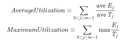
We tend to also look utilization is < ln(2), ln(2) = 0.69 so utilization < 0.69.
Scheduling algorithms/policies:
In a preemptive scheduler threads are suspended by a periodic interrupt, the scheduler chooses a new thread to run, and the return from interrupt will launch this new thread.
In a cooperative or non-preemptive scheduler, the threads themselves must decide when to stop running or give up control usually through a call to a specific function like OS_Suspend
- A cooperative scheduler is not appropriate for real-time systems
A round robin scheduler simply runs the ready threads in circular fashion, giving each the same amount of time to execute.
A weighted round robin scheduler runs the ready threads in circular fashion, but gives threads unequal weighting.
- It can vary the time each thread is allowed to run according to its importance or run important threads more often.
A priority scheduler assigns each thread a priority number, priority may be statically assigned or can be changed dynamically
- These types of schedulers could face the issue that low priority threads may never be run. This situation is called starvation (E.g. if a high priority thread never sleeps or blocks, then the lower priority threads will never run.)
An exponential queue scheduler uses a dynamic scheduling algorithm, with varying priorities and time slices.
- If a thread blocks on I/O, its priority is increased and its time slice is halved.
- If a thread runs to completion of a time slice, its priority is decreased and its time slice is doubled
In an aging scheduler threads have a permanent fixed priority and a temporary working priority, the temporary priority is used to actually schedule threads.
Periodically the OS increases the temporary priority of threads that have not been run in a long time.
Once a thread is run, its temporary priority is reset back to its permanent priority.
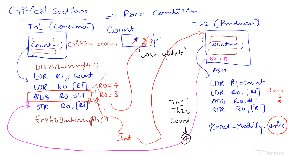
Critical Sections
Race Conditions
- A race condition occurs in a multi-threaded environment when there is a causal dependency between two or more threads. so different behavior occurs depending on the order of execution of two threads.
- It is the problem that occurs when the execution order may affect the outcome.
- The problem occurs because threads manipulate (read/write) a shared object arbitrarily so inconsistent updates to the shared object can happen
- Race condition example: two thread initialize the same port one as input and one as output so the port ends up as either an input or output depending on which thread runs first
A program segment is reentrant it can be interrupted in the middle of its execution and then safely be called again, in more formal words if it can be concurrently executed by two (or more) threads without causing issues
A non-reentrant subroutine will have a section of code called a vulnerable window or critical section, if the code is interrupted during the execution of this sections errors could occur
The root of the critical section issues occur due to the non-atomicity of the read-modify-write operation (or a derivative of this) involved in reading and writing to a shared resource
Usually in embedded systems all I/O ports are considered global variables
An atomic operation is one that once started is guaranteed to finish. In most computers, once an assembly instruction has begun,
the instruction must be finished before the computer can process an interrupt.
To avoid critical section issue we can either remove the access to global variables or implement mutual exclusion,
which means only one thread at a time is allowed to execute in the critical section
A simple way to implement mutual exclusion is to disable interrupts while executing the critical section.
When making code atomic with this method, make sure one critical section is not nested inside another critical section because
if we disable interrupts at the beginning and re-enable interrupts at the end of each critical section there are two disable
interrupt and two enable interrupt functions, interrupts will be incorrectly enabled after the most nested critical section finishes
When we look for critical sections, we look for a global variable that is shared and that we have a non-atomic operation that involves a write.
RTOS Init and Thread Switcher Implementation in a Cortex M4

The RTOS init consists of two main parts the 1) Thread Creation/Initialization and the 2) OS Launch/start, this init and a
3) Thread Switcher are the essential elements needed to implement an RTOS
Thread Creation/Initialization
Definition of TCB
Disable interrupts and config clock (essential peripherals)
Init of linked lists
Init thread stacks
OS Launch/Start
Init Systick, make sure setting the priority of SysTick to be the lowest priority to never interrupt other ISRs
Implement StartOS in assembly and run, in this subroutine the first user thread is launched by setting the stack pointer to the value of the first thread, then pulling all the registers off the stack explicitly.
Thread Switcher: Done in Systick ISR (SysTick_Handler) we switch between tasks/threads taking advantage of the registers automatically pushed to the stack and the return from interrupt functionality
The processor automatically saves eight registers (R0-R3, R12, LR, PC and PSR) on the stack as it suspends execution of the main program and launches the ISR
Disable interrupts because the Thread switcher has read-modify-write operations to the SP and to RunPt
Explicitly save the remaining registers (R4-R11)
Get value of the thread being interrupt which is in RunPt, Register R1 is loaded with this
Save the actual SP into the sp field of the TCB
Choose the next thread in the circular linked list by updating RunPt with the new value.
Set the new thread stack pointer using the newly set RunPt
Explicitly pull eight registers from the stack (R4-R11)
Enable interrupts
LR will contain 0xFFFFFFF9 so he BX LR instruction will automatically pull the remaining 8 registers from the stack, and now the processor will be running the new thread
there are 17 total registers that make up the state of the thread, 16 are saved on the thread stack and the stack pointer itself is stored in the thread control block (TCB).
.c Code Implementation
#define NUMTHREADS 3  // maximum number of threads
#define STACKSIZE 100 // number of 32-bit words in stack 4*100 = 400 bytes for each thread stack

#define THREADFREQ 500 // frequency in Hz

// 1.0. Definition of TCB
typedef struct tcb {
  int32_t* sp;      // pointer to stack, valid for threads not running
  struct tcb* next; // linked-list pointer
} tcb_t;

tcb_t tcbs[NUMTHREADS];
tcb_t *RunPt;
int32_t Stacks[NUMTHREADS][STACKSIZE];

// Function SetInitialStack for step 1.3. Init thread stacks
void SetInitialStack(int i){
  tcbs[i].sp = &Stacks[i][STACKSIZE-16]; // thread stack pointer, make it point to the top of its stack considering we are pushing 16 words
  // Order of registers should match as if context switch happened
  Stacks[i][STACKSIZE-1] = 0x01000000;  // Thumb bit
  //// We are missing the PC which would be at Stacks[i][STACKSIZE-2], it will be initialized later
  Stacks[i][STACKSIZE-3] = 0x14141414;  // R14 == LR
  // The initial values for the rest of the registers do not matter
  Stacks[i][STACKSIZE-4] = 0x12121212;  // R12
  Stacks[i][STACKSIZE-5] = 0x03030303;  // R3
  Stacks[i][STACKSIZE-6] = 0x02020202;  // R2
  Stacks[i][STACKSIZE-7] = 0x01010101;  // R1
  Stacks[i][STACKSIZE-8] = 0x00000000;  // R0
  Stacks[i][STACKSIZE-9] = 0x11111111;  // R11
  Stacks[i][STACKSIZE-10] = 0x10101010; // R10
  Stacks[i][STACKSIZE-11] = 0x09090909; // R9
  Stacks[i][STACKSIZE-12] = 0x08080808; // R8
  Stacks[i][STACKSIZE-13] = 0x07070707; // R7
  Stacks[i][STACKSIZE-14] = 0x06060606; // R6
  Stacks[i][STACKSIZE-15] = 0x05050505; // R5
  Stacks[i][STACKSIZE-16] = 0x04040404; // R4
}

void OS_Init(void){
  // 1.1. Disable interrupts and config clock
  DisableInterrupts();
  BSP_Clock_InitFastest();// set processor clock to fastest speed 80MHz in this case
}

int OS_AddThreads(void(*task0)(void), void(*task1)(void), void(*task2)(void)){
  int32_t status = StartCritical();

  // 1.2. Init of linked lists
  tcbs[0].next = &tcbs[1]; // 0 points to 1
  tcbs[1].next = &tcbs[2]; // 1 points to 2
  tcbs[2].next = &tcbs[0]; // 2 points to 0

  // 1.3. Init thread stacks
  SetInitialStack(0); Stacks[0][STACKSIZE-2] = (int32_t)(task0); // PC
  SetInitialStack(1); Stacks[1][STACKSIZE-2] = (int32_t)(task1); // PC
  SetInitialStack(2); Stacks[2][STACKSIZE-2] = (int32_t)(task2); // PC

  RunPt = &tcbs[0];        // thread 0 will run first

  EndCritical(status);

  return 1; // successful
}

void OS_Launch(uint32_t theTimeSlice){
  // 2.1. Init Systick
  STCTRL = 0;                  // disable SysTick during setup
  STCURRENT = 0;               // any write to current clears it
  SYSPRI3 = (SYSPRI3 & 0x00FFFFFF) | 0xE0000000; // priority 7
  STRELOAD = theTimeSlice - 1; // reload value
  STCTRL = 0x00000007;         // enable, core clock and interrupt arm

  // 2.2. Implement `StartOS` in assembly and run
  StartOS();                   // start on the first task
}

void Scheduler(void){
  RunPt = RunPt->next;  // Round Robin
}

void Task0(void){
  Count0 = 0;
  while(1){ Count0++; }
}

void Task1(void){
  Count1 = 0;
  while(1){ Count1++; }
}

void Task2(void){
  Count2 = 0;
  while(1) { Count2++; }
}

int main(void){
  // 1. Thread Creation/Initialization
  OS_Init(); // initialize clock, disable interrupts
  OS_AddThreads(&Task0, &Task1, &Task2);

  // 2. OS Launch/start
  OS_Launch(BSP_Clock_GetFreq()/THREADFREQ); // interrupts enabled in here

  return 0; // this never executes
}
.asm Code Implementation
; 2.2. Implement `StartOS` in assembly and run
StartOS
    LDR     R0, =RunPt   ; currently running thread
    LDR     R1, [R0]     ; R1 = value of RunPt
    LDR     SP, [R1]     ; new thread SP; SP = RunPt->sp;
    POP     {R4-R11}     ; restore regs r4-11
    POP     {R0-R3}      ; restore regs r0-3
    POP     {R12}
    ADD     SP, SP, #4   ; discard LR from initial stack
    POP     {LR}         ; start location
    ADD     SP, SP, #4   ; discard PSR
    CPSIE   I            ; Enable interrupts at processor level
    BX      LR           ; start first thread

IMPORT Scheduler
; 3. Thread Switcher with C
SysTick_Handler                ; 3.1) Saves R0-R3,R12,LR,PC,PSR
    CPSID   I                  ; 3.2) Prevent interrupt during switch
    PUSH    {R4-R11}           ; 3.3) Save remaining regs r4-11
    LDR     R0, =RunPt         ; 3.4) R0=pointer to RunPt, old thread
    LDR     R1, [R0]           ;      R1 = RunPt
    STR     SP, [R1]           ; 3.5) Save SP into TCB
    PUSH    {R0,LR}
    BL      Scheduler          ; 3.6) RunPt = RunPt->next
    POP     {R0,LR}
    LDR     R1, [R0]           ; 3.6) R1 = RunPt, new thread casue R0 still points to RunPt
    LDR     SP, [R1]           ; 3.7) new thread SP; SP = RunPt->sp;
    POP     {R4-R11}           ; 3.8) restore regs r4-11
    CPSIE   I                  ; 3.9) tasks run with interrupts enabled
    BX      LR                 ; 3.10) restore R0-R3,R12,LR,PC,PSR

; 3. Alternative Thread Switcher implementation in pure assembly
SysTick_Handler_asm            ; 3.1) Saves R0-R3,R12,LR,PC,PSR
    CPSID   I                  ; 3.2) Prevent interrupt during switch
    PUSH    {R4-R11}           ; 3.3) Save remaining regs r4-11
    LDR     R0, =RunPt         ; 3.4) R0=pointer to RunPt, old thread
    LDR     R1, [R0]           ;      R1 = RunPt
    STR     SP, [R1]           ; 3.5) Save SP into TCB
    LDR     R1, [R1,#4]        ; 3.6) R1 = RunPt->next
    STR     R1, [R0]           ; 3.6) RunPt = R1
    LDR     SP, [R1]           ; 3.7) new thread SP; SP = RunPt->sp;
    POP     {R4-R11}           ; 3.8) restore regs r4-11
    CPSIE   I                  ; 3.9) tasks run with interrupts enabled
    BX      LR                 ; 3.10) restore R0-R3,R12,LR,PC,PSR
Semaphores
A Semaphore is a counter with three functions: OS_InitSemaphore to init the semaphore and OS_Wait & OS_Signal/OS_Post//OS_Set which are used at run time to provide synchronization between threads
Semaphores are used to implement:
- Synchronization (as a Condition Variable or Event flag): This means ordering of execution is controlled. For example a thread cannot try to consume data that hasn't been produced, so if it attempts to consume data, it should block so that when some other thread produces it then it gets informed so it can consumed and its activity is synchronized
- Mutual exclusion (as a Mutex): This means only one thread accessing a resource at a certain time
A semaphore that can only be 0 or 1 is called a binary semaphore.
A spin-lock semaphore is the simplest way of implementing a semaphore in which a thread just waits for the semaphore to be posted
// If s is initialized as 0 the Semaphore can be used as a event flag, wait to wait for event and post to signal event
// If s is initialized as 1 the Semaphore can be used as a mutex, wait to lock and post to unlock the mutex
void OS_SpinLock_Init(int32_t *s, int32_t value){
    *s = value;
}

void OS_SpinLock_Wait(int32_t *s) {
  DisableInterrupts();
  while((*s) == 0) {    // Spin-lock loop
    EnableInterrupts(); // interrupts can occur here
    DisableInterrupts();
  }
  (*s) = (*s) - 1;
  EnableInterrupts();
}

void OS_SpinLock_Signal(int32_t *s) {
  DisableInterrupts();
  (*s) = (*s) + 1;
  EnableInterrupts();
}
Mailbox Semaphore Synchronization: We can use semaphores to implement a more structured mailbox synchronization mechanism whis is generally used in a producer-consumer situation between two threads
//// Spin-Lock Blocking implementation
// OS_MailBox init
uint32_t Mail;  // shared data
int32_t Send = 0; // semaphore
int32_t Ack = 0;  // semaphore

// Spin-Lock Blocking send implementation using Ack
void OS_MailBox_Send(uint32_t data) {
  Mail = data;
  OS_Signal(&Send);
  OS_Wait(&Ack);
}

// Spin-Lock Blocking recv implementation using Ack
uint32_t OS_MailBox_Recv(void) {
  uint32_t theData;
  OS_Wait(&Send);
  theData = Mail; // read mail
  OS_Signal(&Ack);
  return theData;
}
//// Spin-Lock Blocking, Non-Blocking mixed implementation
// OS_MailBox init
uint32_t Mail = 0 // shared data
int32_t Send = 0 // semaphore

// Spin-Lock Non-blocking send implementation if mailbox is already full that data will be lost.
void OS_MailBox_Send(uint32_t data){
  Mail = data;
  if(!Send) {
    OS_Signal(&Send);
  }
}

// Spin-Lock Blocking recv
uint32_t OS_MailBox_Recv(void){
  OS_Wait(&Send);
  return Mail;
}
3. Time Management
Cooperation and Suspending Threads
When a thread can longer make process the smart thing to do is give up control so other task can run,
to implement this and OS usually has a OS_Suspend function or a similar method to give up control
A Cooperative Semaphore is one that instead of waiting, gives up control to other task for example by calling a OS_Suspend function
One way to suspend a thread is to trigger a Scheduler interrupt
(E.g. trigger a SysTick interrupt by writing INTC Systick register INTCTRL = 0x04000000
and resetting the counter to give a full time slice to the next thread).
void OS_Suspend(void){
  STCURRENT = 0;        // reset counter
  INTCTRL = 0x04000000; // trigger SysTick
}
Blocking
Blocking in an OS come from the idea of letting a thread block and wake up only when the resource is available.
A blocking semaphore is a semaphore that will prevent a thread from running when the thread needs a resource that is unavailable, it puts threads in a blocked state. Reason to use Blocking Semaphores
- Efficiency: With blocking semaphores, a thread will not run unless it has useful work it can accomplish. Because it is wasteful to launch a thread you know can’t run, only to suspend itself 10 μs later.
- Fairness: when the status of a resource goes from busy to available, that all threads waiting on the resource should get equal chance.
- Priority: To implement a priority thread scheduler we need blocking semaphores we cannot use spin-lock semaphores for this
A thread is in the blocked state when it is waiting for some external event like input/output it is the semaphore function OS_Wait
that will block a thread if it needs to wait.
- This can be implemented by adding a field to the TCB that contains a pointer to the semaphore on which this thread is blocked
A Counting Semaphore is a way of implementing a Blocking Semaphore which holds a meaning in its count,
usually represents the number of threads blocked on this resource.
1: means it's free, the resource is available.0: means the resource is not available but nobody's blocked.<0: represents the number of threads blocked waiting for the resource guarded by this semaphore besides the thread using the resource. E.g. if the semaphore is -2, it means one thread is using the resource and two other threads are blocked, waiting to use it.
    // Wait Decrements
    void OS_CountingSem_Wait(int32_t *s){
      DisableInterrupts();
      (*s) = (*s) - 1;
      if((*s) < 0) {
        RunPt->blocked = s; // reason it is blocked
        EnableInterrupts();
        OS_Suspend();       // run thread switcher
      }
      EnableInterrupts();
    }

    // Signal Increments
    void OS_CountingSem_Signal(int32_t *s){
      tcb_t *pt;
      DisableInterrupts();
      (*s) = (*s) + 1;
      if((*s) <= 0) {
        pt = RunPt->next;   // search for a thread blocked on this semaphore
        while(pt->blocked != s) {
          pt = pt->next;
        }
        pt->blocked = 0;    // wakeup this one
      }
      EnableInterrupts();
    }

    // In this implementation calling the OS_CountingSem_Signal will not invoke the thread switcher.
    // So during the thread switch, the OS needs to search the circular linked-list for a thread with a blocked field equal to zero
    // the woken up thread in the signal call is just a possible candidate in the next scheduler iteration.
    // Because of this we need to update the Scheduler accordingly
    void Scheduler(void){
      RunPt = RunPt->next;    // run next thread not blocked
      while(RunPt->blocked) {  // skip if blocked
        RunPt = RunPt->next;
      }
    }
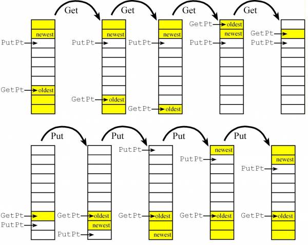
FIFO Example: If a thread needs information from a FIFO (calls Get),
then it will be blocked if the FIFO is empty (because it cannot retrieve any information.)
Also, if a thread outputs information to a FIFO (calls Put), then it will be blocked if the FIFO is full (because it cannot save its information.)
Producer-Consumer FIFO
- A common way to implement a Producer-Consumer FIFO buffer is using Blocking Semaphores
- The function
Put will store data in the FIFO, and the function Get will remove data (returning the oldest data)
- A system is considered to be deterministic if when the system is run with the same set of inputs, it produces identical responses. Most real-time systems often require deterministic behavior
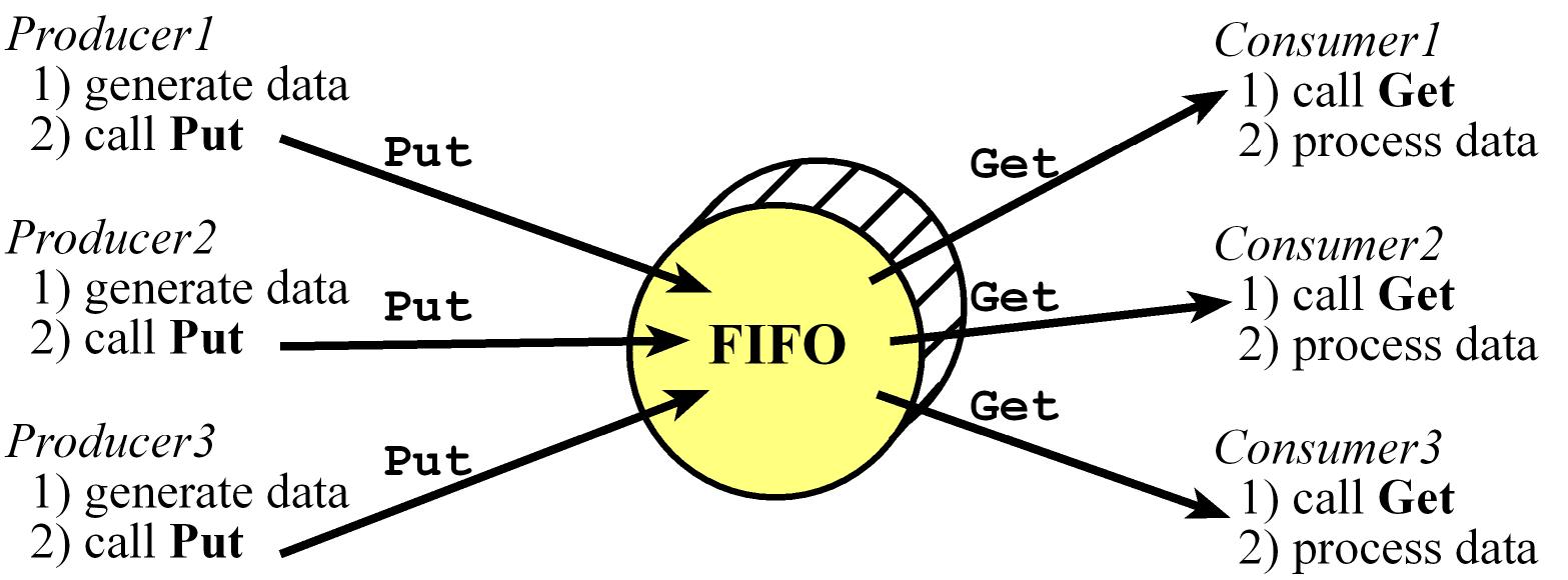
Two-pointer three-semaphore implementation of a FIFO
- In this implementation we'll block producers when the FIFO is full and block consumers when the FIFO is empty,
- This implementation works if the producer and consumer are main threads, but cannot be used if either the producer or consumer is an event thread or ISR becasue we assume the consumer needs data to proceed
#define FIFOSIZE 10       // FIFO Size

uint32_t volatile *PutPt; // put next. Points to the next location to be put to.
uint32_t volatile *GetPt; // get next. Points to the oldest item
uint32_t static Fifo[FIFOSIZE];
int32_t CurrentSize;   // Specifies the number of elements currently in the FIFO. 0 means FIFO empty
int32_t RoomLeft;      // Specifies the how many more elements could be put into the FIFO. 0 means FIFO full
int32_t FIFOmutex;     // exclusive access to FIFO, mutex to protect the pointers

// Initialize FIFO
void OS_Fifo_Init(void){
  PutPt = GetPt = &Fifo[0]; // Empty
  OS_InitSemaphore(&CurrentSize, 0);
  OS_InitSemaphore(&RoomLeft, FIFOSIZE);
  OS_InitSemaphore(&FIFOmutex, 1);
}

void OS_Fifo_Put(uint32_t data){
  OS_Wait(&RoomLeft);  // RoomLeft is decremented by Fifo_Put signifying there is space for one less element. Check if FIFO is full and block if it is
  OS_Wait(&FIFOmutex);
  *(PutPt) = data;     // Put
  PutPt++;             // place to put next
  if(PutPt == &Fifo[FIFOSIZE]){
    PutPt = &Fifo[0];  // wrap
  }
  OS_Signal(&FIFOmutex);
  OS_Signal(&CurrentSize); // CurrentSize is incremented by Fifo_Put signifying one more element
}

uint32_t OS_Fifo_Get(void){
  uint32_t data;
  OS_Wait(&CurrentSize);  // CurrentSize is decremented by Fifo_Get signifying one less element. Check if FIFO is empty and block if it is
  OS_Wait(&FIFOmutex);
  data = *(GetPt);     // get data
  GetPt++;             // points to next data to get
  if(GetPt == &Fifo[FIFOSIZE]){
    GetPt = &Fifo[0];  // wrap
  }
  OS_Signal(&FIFOmutex);
  OS_Signal(&RoomLeft); // RoomLeft incremented by Fifo_Get signifying there is space for one more element.
  return data;
}
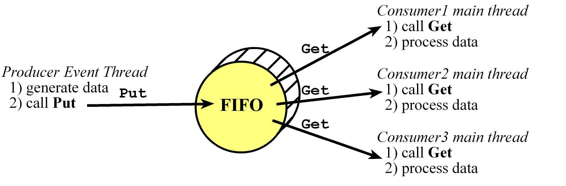
Two-pointer two-semaphore implementation of a FIFO
- This works If there is one producer as an event thread coupled with one or more consumers as main threads
- In this implementation if the FIFO is full when the producer calls Put, then that data will be lost
- This Put function cannot be called by multiple producers because of the read-modify-write sequence to
PutPt.
#define FIFOSIZE 10       // FIFO Size

uint32_t volatile *PutPt; // put next. Points to the next location to be put to.
uint32_t volatile *GetPt; // get next. Points to the oldest item
uint32_t static Fifo[FIFOSIZE];
int32_t CurrentSize;      // Specifies the number of elements currently in the FIFO. 0 means FIFO empty
int32_t FIFOmutex;        // Exclusive access to FIFO, needed to prevent two consumers from reading the same data
uint32_t LostData;

// initialize FIFO
void OS_Fifo_Init(void) {
  PutPt = GetPt = &Fifo[0]; // Empty
  OS_InitSemaphore(&CurrentSize, 0);
  OS_InitSemaphore(&FIFOmutex, 1);
  LostData = 0;
}

int OS_FIFO_Put(uint32_t data) {
  if(CurrentSize == FIFOSIZE) {
    LostData++;      // Returns an error (-1) if the data was not saved because the FIFO was full
    return -1;
  }

  *(PutPt) = data;    // Put
  PutPt++;            // place for next
  if(PutPt == &Fifo[FIFOSIZE]){
    PutPt = &Fifo[0]; // wrap
  }
  OS_Signal(&CurrentSize);
  return 0;
}

uint32_t OS_FIFO_Get(void) {
  uint32_t data;
  OS_Wait(&CurrentSize); // Check if FIFO is empty and block if it is empty
  OS_Wait(&FIFOmutex);
  data = *(GetPt);    // get data
  GetPt++;            // points to next data to get
  if(GetPt == &Fifo[FIFOSIZE]){
    GetPt = &Fifo[0]; // wrap
  }
  OS_Signal(&FIFOmutex);
  return data;
}
If there is only one consumer (besides the only one producer) we don't need the FIFOmutex so we can remove it from the OS_FIFO_Get and convert this to a one-semaphore implementation of a FIFO
Sleeping
Sleeping is another way a thread gives up control and implement a 'periodic' task that runs approximately every certain amount
of time (It doesn't have an exact period of execution). Usually used for Debouncing or other operatiosn that need a delay but not a strict one
Usually and OS implements an OS_Sleep function that will make a thread dormant for a finite time and after that time the tread
will be active again (not run, just active to be considered to run again by the scheduler)
Implementation considerations
- adding a counter field to the TCB to know if a thread is sleeping, checking this in the scheduler
- adding a periodic task that decrements the sleep counter.
- when a thread wants to sleep it will set its
Sleep field and call the scheduler to switch tasks
- The sleep period represented by the
Sleep field is not an exact time delay because when reacheing 0, the thread is not immediately run it just active so it will be considered to run again by the scheduler
    void Timer_ISR(void) {
      uint32_t i = 0;
      while (i < NUMTHREADS) {
        if(RunPt->sleep > 0) {
          RunPt->sleep--;
        }
        RunPt = RunPt->Next;
        i++;
      }
    }

    void OS_Sleep(uint32_t n) {
      RunPt->sleep = n;
      OS_Suspend();
    }

    void Scheduler(void) {
      RunPt = RunPt->next; // skip at least one
      while((RunPt->sleep) || (RunPt->blocked)) {
        RunPt = RunPt->next; // find one not sleeping and not blocked
      }
    }
4. Real-time Systems
- A data adquisition system usually require priority in their implementation
- A MACQ (Multiple Access Circular Queue) is an enhanced FIFO usually used in DSP (Digital Signal Processing) Application,
where the put and get are a little different than in a regular FIFO, we don't always just get one item, we may get multiple items.
and a get shouldn't remove the item from the queue. It just retains the old values, and they get overwritten by new data that comes in.
OS Debouncing a switch on TM4C123
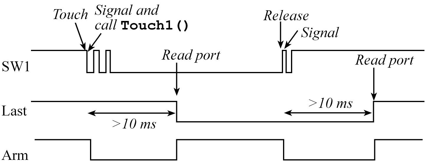
- Considering we want to remove the bounce so there is one software event attached to the switch touch and another for the release
- Configure it to trigger an interrupt on both edges
- Signal a semaphore on the ISR and disarm the interrupt, so the semaphore is incremented once per touch or once per release.
- Wait on that semaphore, sleep for 10ms and then read the switch at a time the switch is guaranteed to be stable.
int32_t SW1,SW2;
uint8_t last1,last2;

void Switch_Init(void) {
  SYSCTL_RCGCGPIO_R |= 0x20; // activate clock for Port F
  OS_InitSemaphore(&SW1,0);  // initialize semaphores
  OS_InitSemaphore(&SW2,0);
  GPIO_PORTF_LOCK_R = 0x4C4F434B; // unlock GPIO Port F
  GPIO_PORTF_CR_R = 0x1F;         // allow changes to PF4-0
  GPIO_PORTF_DIR_R &= ~0x11; // make PF4,PF0 in
  GPIO_PORTF_DEN_R |= 0x11;  // enable digital I/O on PF4,PF0
  GPIO_PORTF_PUR_R |= 0x11;  // pullup on PF4,PF0
  GPIO_PORTF_IS_R &= ~0x11;  // PF4,PF0 are edge-sensitive
  GPIO_PORTF_IBE_R |= 0x11;  // PF4,PF0 are both edges
  GPIO_PORTF_ICR_R = 0x11;   // clear flags
  GPIO_PORTF_IM_R |= 0x11;   // arm interrupts on PF4,PF0
  NVIC_PRI7_R = (NVIC_PRI7_R&0xFF00FFFF)|0x00A00000; // priority 5
  NVIC_EN0_R = 0x40000000;   // enable interrupt 30 in NVIC
}

void GPIOPortF_Handler(void) {
  if(GPIO_PORTF_RIS_R&0x10){  // poll PF4
    GPIO_PORTF_ICR_R = 0x10;  // acknowledge flag4
    OS_Signal(&SW1);          // signal SW1 occurred
    GPIO_PORTF_IM_R &= ~0x10; // disarm interrupt on PF4
  }
  if(GPIO_PORTF_RIS_R&0x01) {  // poll PF0
    GPIO_PORTF_ICR_R = 0x01;  // acknowledge flag0
    OS_Signal(&SW2);          // signal SW2 occurred
    GPIO_PORTF_IM_R &= ~0x81; // disarm interrupt on PF0
  }
  OS_Suspend(); // Explicit task switch
}

void Switch1Task(void) {  // high priority main thread
  last1 = GPIO_PORTF_DATA_R&0x10;
  while(1) {
    OS_Wait(&SW1);       // wait for SW1 to be touched/released
    if(last1) {          // was previously not touched
      Touch1();          // user software associated with touch
    } else {
      Release1();        // user software associated with release
    }
    OS_Sleep(10);        // wait for bouncing to be over
    last1 = GPIO_PORTF_DATA_R&0x10;
    GPIO_PORTF_IM_R |= 0x10; // rearm interrupt on PF4
    GPIO_PORTF_ICR_R = 0x10; // acknowledge flag4
  }
}

void Switch2Task(void) {  // high priority main thread
  last2 = GPIO_PORTF_DATA_R&0x01;
  while(1) {
    OS_Wait(&SW2);      // wait for SW2 to be touched/released
    if(last2) {         // was previously not touched
      Touch2();         // user software associated with touch
    }else {
      Release2();       // user software associated with release
    }
    OS_Sleep(10);       // wait for bouncing to be over
    last2 = GPIO_PORTF_DATA_R&0x01;
    GPIO_PORTF_IM_R |= 0x01; // rearm interrupt on PF0
    GPIO_PORTF_ICR_R = 0x01; // acknowledge flag0
  }
}
Priority
Turn around time is the time elapsed from when a thread arrives till it completes execution
Response time is the time elapsed from when a thread arrives till it starts execution. Round robin minimizes response time
Priority inversion is a problem or condition usually caused when a high-priority thread is waiting on a resource owned by a low-priority thread.
in this situation a low priority task is acting as if it is bigger than a high priority for some time so the priorities are "inverted".
A solution for this is with priority inheritance, once a high-priority thread blocks on a resource, the thread holding that resource is granted a
temporary priority equal to the priority of the high-priority blocked thread, once the thread releases the resource, its priority is returned to its original value.
This can be implemented with a semaphore protocol called priority ceiling
The Rate Monitonic Theorem main idea is to assign high priority to tasks that generate a lot of blocking (I/O) and low priority to tasks which are processor intensive
Multi-level feedback queue has good performance for response time and the turn around time.
Priority Scheduler Implementation
- Define a new field in the TCB that holds the priority of the thread (0 as the highest priority and 254 as the lowest)
- The idea is to search and find the highest priority thread, which is neither blocked nor sleeping and run it, if there
are threads with equal priority, these threads will be run in a round robin fashion.
void Scheduler(void) { // every time slice
  uint32_t max = 255; // max
  tcbType *pt;
  tcbType *bestPt;
  pt = RunPt;         // search for highest thread not blocked or sleeping
  do{
    pt = pt->next;    // skips at least one
    if((pt->Priority < max) && ((pt->BlockPt) == 0) && ((pt->Sleep) == 0)){
      max = pt->Priority;
      bestPt = pt;
    }
  } while(RunPt != pt); // look at all possible threads
  RunPt = bestPt;
}
Priority Scheduler
priority scheduler is flexible in two ways.
- When can layer our application into levels of priority
- We can use a priority scheduler for any triggering event, hardware or software. We simply make that triggering event call
OS_Signal and OS_Suspend to signals the semaphore on the appropriate event and the user code runs as a main thread.
With priority scheduler, we can place time-critical tasks as high priority threads.
We will block these time-critical tasks waiting on an event (semaphore) and when the event occurs we signal its semaphore.
Because we now have a high priority thread not blocked, the scheduler will run it immediately. This will make them run periodically with very little jitter.
int32_t TakeSoundData; // binary semaphore
void RealTimeEvents(void){
  OS_Signal(&TakeSoundData);
  OS_Suspend();
}
void Task0(void){
  while(1){
    OS_Wait(&TakeSoundData); // signaled every 1ms
    Profile_Toggle0();       // viewed by the logic analyzer to know Task0 started
    // time-critical software here
  }
}

int main(void){
  OS_Init();
  // other initialization
  OS_InitSemaphore(&TakeSoundData,0);
  OS_AddThreads(&Task0,0, &Task1,1, &Task2,2);
  BSP_PeriodicTask_Init(&RealTimeEvents, 1000,0);
  OS_Launch(BSP_Clock_GetFreq()/THREADFREQ); // doesn't return
  return 0; // this never executes
}
Available/Popular RTOS
- Deployed in over 1.5 billion devices, VxWorks by Wind River is the world’s leading real-time operating system (RTOS).
VxWorks delivers hard real-time performance, determinism, and low latency along with the scalability, security, and safety required
for aerospace and defense, industrial, medical, automotive, consumer electronics, networking, and other industries.
VxWorks has become the RTOS of choice when certification is required. It is deployed on architectures as the X86, ARM Cortex-A series, and Freescale QorIQ, but not on the Cortex M
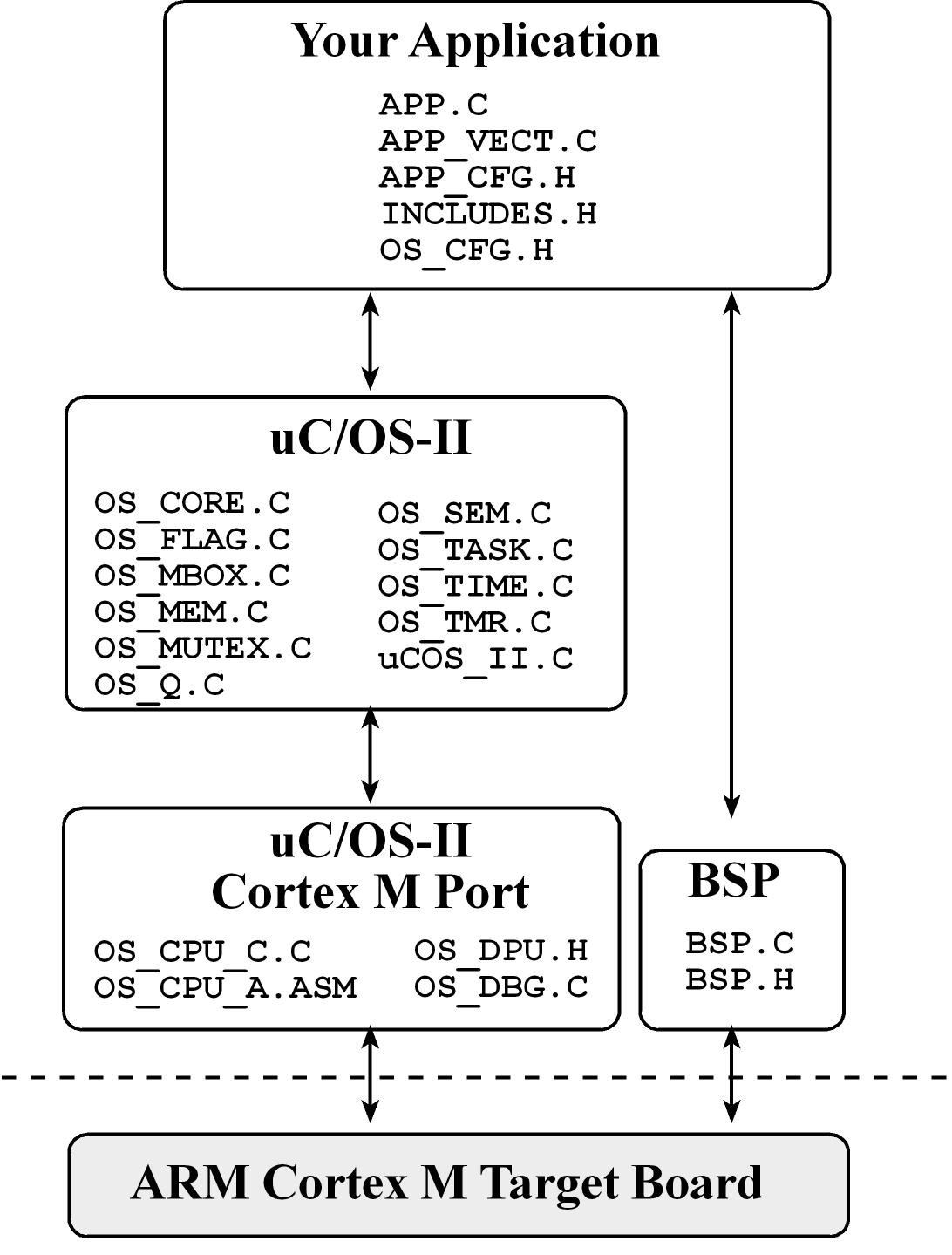
Micrium μC/OS-II
- Micrium μC/OS-II is a portable, ROMable, scalable, preemptive (with priorities), real-time deterministic multitasking kernel for microprocessors
- Each thread in Micrium μC/OS-II has a unique priority (no two threads have equal priority), the threads will run in a deterministic pattern
- Works with 10 threads by default but allows expansion to 255 threads (scaled between 5 kibibytes to 24 kibibytes)
- In cortex M4 implements OS context switch in
PendSV ISR
- μC/OS-II includes:
- semaphores
- event flags
- mutual-exclusion semaphores that eliminate unbounded priority inversions
- message mailboxes and queues
- task, time and timer management
- fixed sized memory block management.
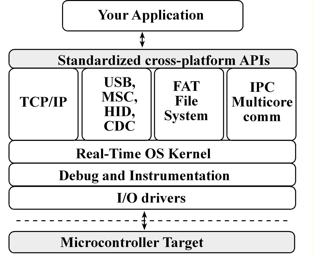
Texas Instruments RTOS (TI-RTOS)
- TI-RTOS scales from a real-time multitasking kernel to a complete RTOS solution
- TI-RTOS is provided with full source code and requires no up-front or runtime license fees
- TI-RTOS combines a real-time multitasking kernel with additional middleware components including TCP/IP and USB stacks, a FAT file system, and device drivers
FreeRTOS
- FreeRTOS only provides the core real-time scheduling functionality, inter-task communication, timing and synchronization primitives. This means it is more accurately described as a real-time kernel, or real-time executive
- FreeRTOS is licensed under a modified GPL and can be used in commercial applications under this license without any requirement to expose your proprietary source code.
- PendSV handler that implements the context switch
5. File Systems

Fragmentation
Fragmentation is a problem related to wasted space
Files systems are usually implemented as a sequence of sectors
A sector is a unit of storage, each sector is the smallest amount of storage we can use to save data and has a fixed size (usually ~512 bytes) so whole sectors will be allocated to a file.
One of the resposabilities of the file system is to translate the logical address to the physical address.
- information in a file as a simple linear array of bytes , the "logical" address is considered as the index into this array

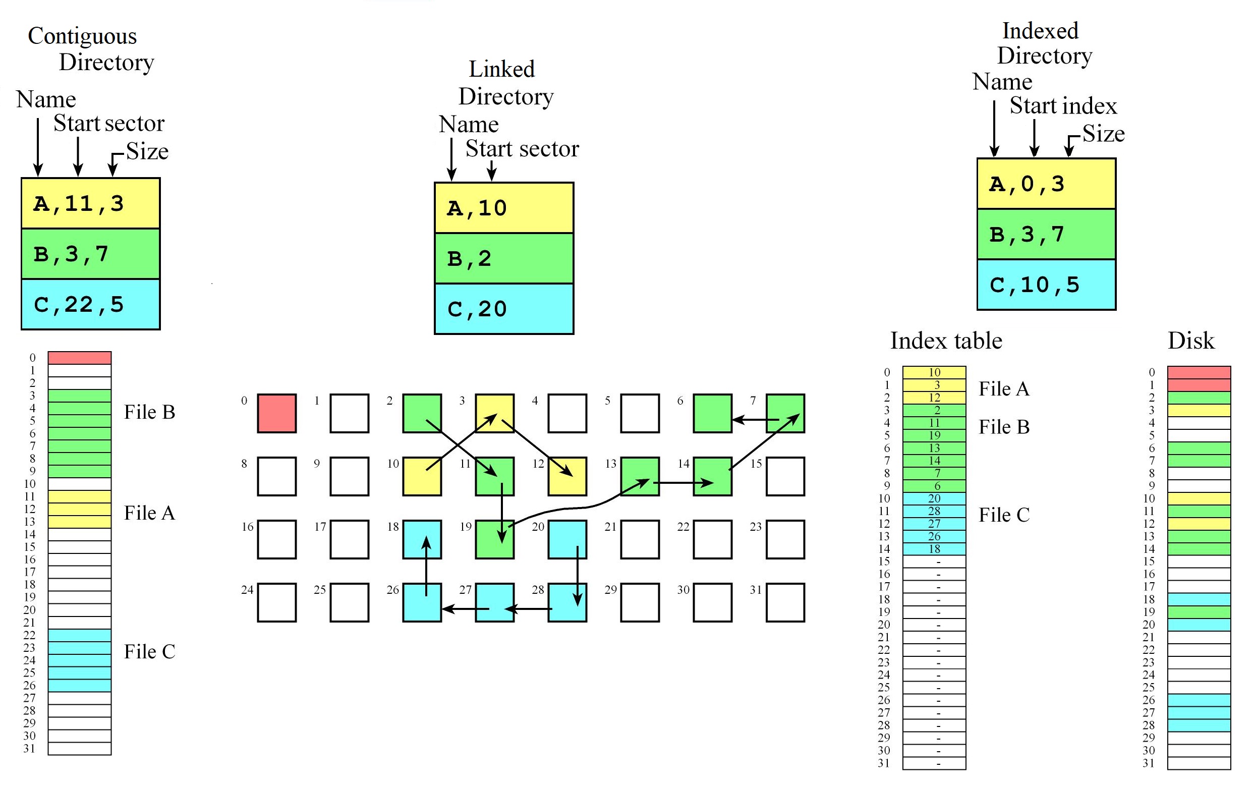
- Components of the file system
- Directory: Where do we find the list of files and what information do we keep of each file
- Allocation: How to allocate contents of a file, translate from logical to physical
- Free-space management How do we manage and optimize free space
Types of Fragmentation
Internal fragmentation
- It is storage that is allocated for the convenience of the operating system but contains no information,
- It is space used for the FS implementation convenience and it's inside the allocated region "internal".
- The wasted allocated space is unavaliable to the FS to use and in this case is called file slack or slack space
- For example for a file we may allocated a sector or cluster of sectors and although the file does not use all this space it is left because simplifies the FS organization, it's implementation and makes it easier to grow files
External fragmentation
- It exists when the largest file that can be allocated is less than the total amount of free space on the disk.
- It is "external" cause refers to the fact that the unusable storage is outside the allocated regions.
- The total number of free sectors exceeds a file request but is not contiguous and because it's not contiguous, the request cannot be met.
- This problem exists when an application allocates and deallocates regions of storage of varying sizes, so
over time free storage becomes divided into many small pieces. The result is that although free storage is available,
it is effectively unusable because it is divided into pieces that are too small to satisfy the demands of the application.
- For example suppose a new file with five sectors is requested, but the largest contiguous chunk of free disk space is only three
sectors long so even if there are ten free sectors or more in total (the sum of all individual chunks), one still cannot allocate the requested file with five sectors
Allocation
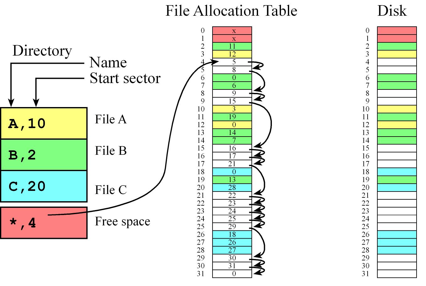
File Allocation Table (FAT)
- The file allocation table (FAT) is a mixture of indexed and linked allocation
- Each directory entry contains a file name and the initial sector of a file while the FAT table contains a linked list of sectors for each file
- We can chain sectors together in the FAT to manage free space
- First sector (index 0) for directory and second for the table (index 1)
- It has the flexibility of making it very easy to grow or shrink a file
- Fast if Directory and table are in RAM we can randomly access any byte in the disk by doing one disk read.
- Size of the entries in the table and the total entries of the table is determined by the number of sectors
- e.g. if we have 32 sectors in the disk then we need at least 5 bits in each entry
- we have an entry in the file allocation table for every sector on the disk.
Memory
File System Implementation (Internal flash Storage device driver)
SD FS implementations low-level eDisk and a high-level FAT16 file system
The TM4C123 and MSP432 have 256 kB of internal flash, existing from addresses 0 to 0x0003FFFF
Normally, internal flash is used to save the machine code of our software. However, we can allocate part of it (half for example which is 2^17 = 128 kibibytes = 128 kB) to create a solid state disk
let each sector be 2^p bytes and will partition the 2^17 = 128 kB disk into 2^m sectors so m+p=17
The smallest block that we can erase on the TM4C123 is 1024 bytes = 1 kB
Operations:
- erase (set bits to 1)
int Flash_Erase(uint32_t addr);
- program (set bits to data)
int Flash_Write(uint32_t addr, uint32_t data); and int Flash_WriteArray(uint32_t *source, uint32_t addr, uint16_t count);
- read, no need for specific API since software simply reads from the memory address in the usual manner.
Implementation details of Write once FS:
- The 128k flash memory is erased only once (formatting)
- Partitioned into 256 sectors of 512 bytes/sector so we can append data to a file in chunks of 512 bytes but cannot delete data or files
- file names will be single 8-bit numbers (0 to 254, maximum of 255)
- flush (backup to disk) the file system before powering down
- One sector will be reserved for the operating system to manage the directory and allocation scheme
- Use the sector address
255=0xFF to mean null-pointer, and use sector number 255 as the directory.
6. Bluetooth Low Energy
A network is a collection of interfaces that share a physical medium (which refers to the actual physical medium, like a wire) and a data protocol (which is how data is encoded in the communication channel.), it provides the transfer of information as well as the mechanisms for process synchronization.
The topology of a network defines how the components are interconnected, shape of how the network is connected.
A full duplex channel allows data to transfer in both directions at the same time (E.g. Ethernet, SPI, UART...). In a half duplex system, data can transfer in both directions but only in one direction at a time (E.g. CAN, I2C, etc.). A simplex channel allows data to flow in only one direction.
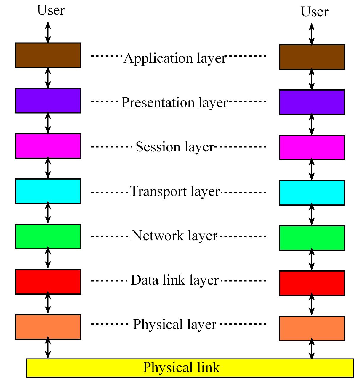
The International Standards Organization (ISO) defines a 7-layer model called the Open Systems Interconnection (OSI) which t provides a standard way to classify network components and operations.
- The Physical layer refers to the medium through which we are going to communicate, includes connectors, bit formats, and a means to transfer energy.
- he Data link layer includes error detection and control across a single link
- The Network layer defines end-to-end multi-hop data communication.
- The Transport layer provides connections and may optimize network resources.
- The Session layer provides services for end-user applications such as data grouping and check points
- The Presentation layer includes data formats, transformation services.
- The Application layer provides an interface between network and end-user programs.
CAN - Controller Area Network
CAN is a high-integrity serial data communications bus that is used for real-time applications
- Operate at data rates of up to 1 Mbits/second
- Has excellent error detection and confinement capabilities
- Can network can have up to 112 nodes
- It based on the "broadcast communication mechanism" rather than an "address-based protocol"
- It is easy to add stations to an existing CAN network.
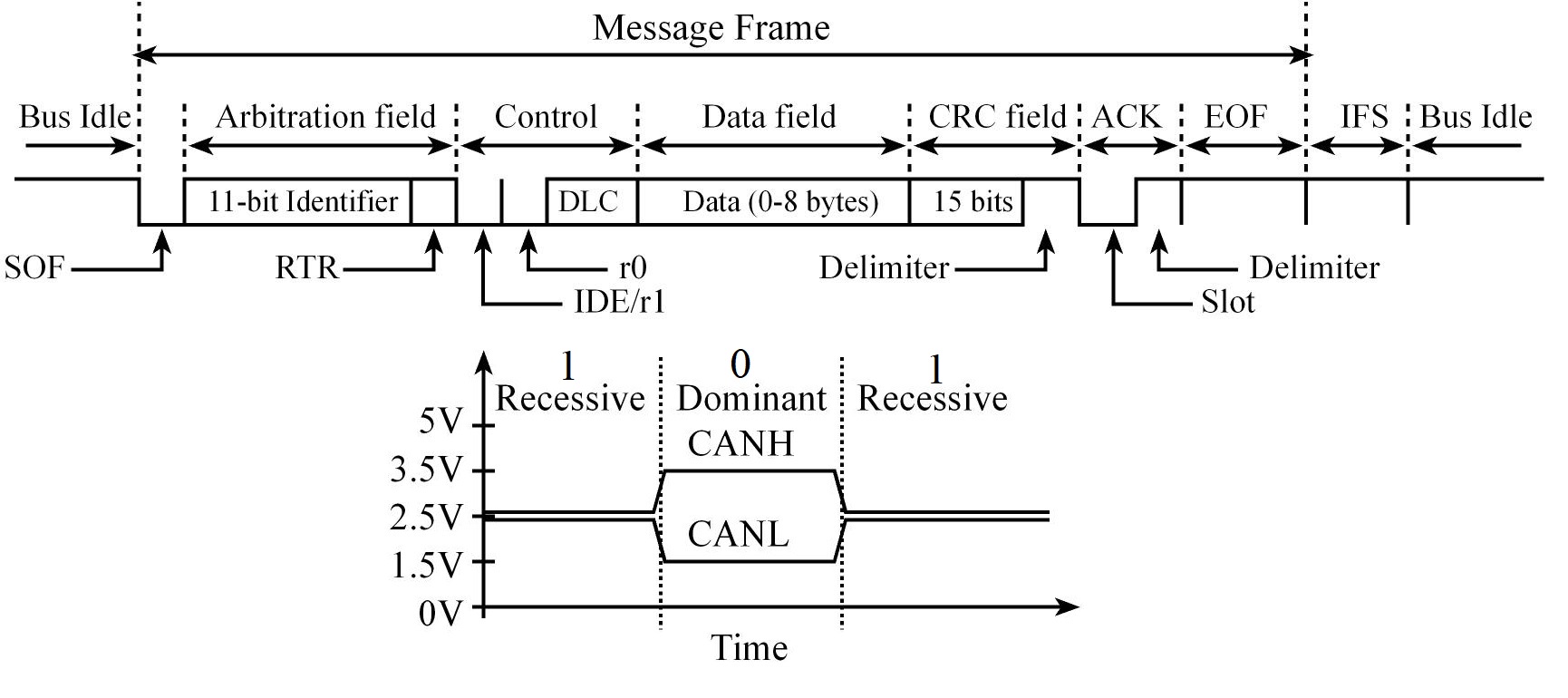
In CAN there are dominant and recessive states on the transmitter, if one or more nodes are sending a dominant state, it will override any nodes attempting to send a recessive state.
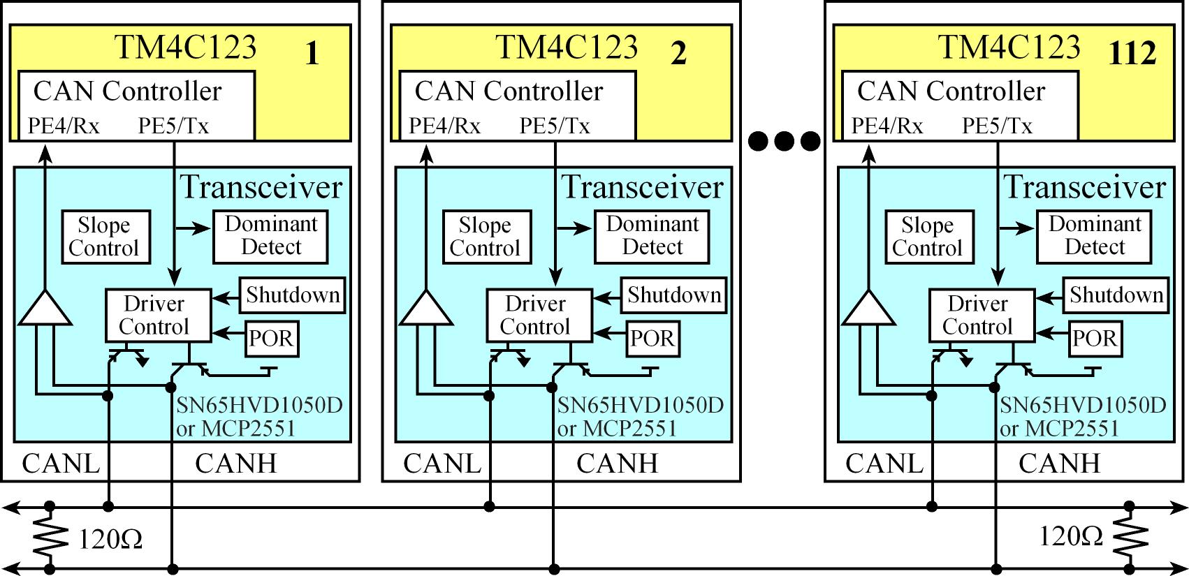
CAN components
- CAN bus consisting of two wires (CANH, CANL) with 120Ω termination resistors on each end, each node taps into that cable.
- The CAN Transceiver, which handles the voltage levels and interfacing the separate receive (RxD) and transmit (TxD) signals onto the CAN bus.
- It is a high-speed, fault-tolerant device that serves as the interface between a CAN protocol controller (located in the microcontroller) and the physical bus
- It is capable of driving the large current needed for the CAN bus and has electrical protection against defective stations
- The CAN controller, which is hardware built into the microcontroller, and it handles message timing, priority, error detection, and retransmission
- The software that handles the high-level functions of generating data to transmit and processing data received from other nodes.
A transceiver is a device capable of transmitting and receiving on the same channel.
In a CAN system, messages are identified by their contents rather by addresses. Each message sent on the bus has a unique identifier, which defines both the content and the priority of the message.
CAN Message types:
- Data Frame
- Remote Frame
- Error Frame
- Overload Frame
The Data Frame
- Arbitration Field determines the priority of the message and contains:
- Identifier:
- For Standard CAN 2.0A, it consists of an .
- For the Extended CAN 2.0B, there is a 29-bit Identifier
- Remote transmission request (RTR) bit
0: (dominant) for data frames1: (recessive) for remote request frames
- Control Field contains:
- DLC: specifies the number of data bytes
- Data Field contains the data, from zero to eight bytes of data
- CRC Field contains a 15-bit checksum used for error detection, it's value is based on the remainder of a polynomial division of the contents
- ACK Field contains an Acknowledgement bit
To transmit a message, the software must set the Identifier (11-bit or 28-bit), set the 4-bit DLC, and give the 0 to 8 bytes of data,
the receivers can define filters on the identifier field, so only certain message types will be accepted and when it is
the software can read the identifier, length, and data.
The Intermission Frame Space (IFS) separates one frame from the next.
The number of bits in a CAN message frame is determined by the ID (11 or 29 bits) and the Data fields (from 0 to 64 bits in mutiples of 8, in other words rom 0 to 8 bytes)
In CAN bandwidth and response time are affected by message priority, the identifier with the lowest binary number has the highest priority
In order to resolve a bus access conflict, each node in the network observes the bus level bit by bit, a process known as bit-wise arbitration.
The dominant state overwrites the recessive state. All nodes with recessive transmission but dominant observation immediately lose the competition for bus access and become receivers of the message with the higher priority (become listeners only),
Buetooth Fundamentals
Bluetooth is wireless medium and a data protocol that connects devices together over a short distance
- Classified as personal area network (PAN) because it implements communication within the range of an individual person. Operates from 1 to 100 meters
At the highest level, we see Bluetooth devices implement profiles. A profile is a suite of functionalities that support a certain type of communication
E.g. the Advanced Audio Distribution Profile (A2DP) can be used to stream data and the most generic one the Generic Attribute Protocol (GATT) within the GATT there can be one or more services
Within a service there may be one or more characteristics. A characteristic is user or application data that is transmitted
from one device to another across the network (characteristic = data). They have universally unique identifier (UUID) which is a 128-bit (16-byte) number.
Characteristic has a property which define what can be do with it like read, write or notify and one or more descriptors. Descriptors may be information like its name and its units. UUIDs are passed across the network.
Handles are a mechanism to identify characteristics within the device. A handle is a pointer to an internal data structure
within the GATT that contains all the information about that characteristic, they are not passed across the Bluetooth network; rather,
they are used by the host and controller to keep track of characteristics.
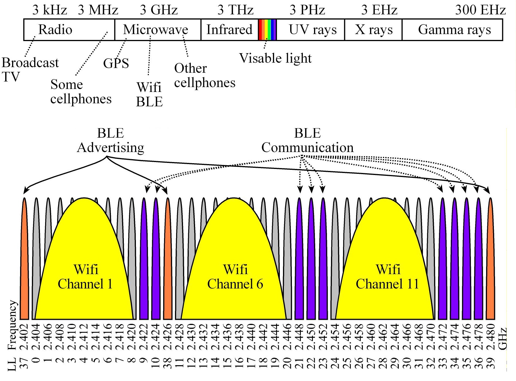
Bluetooth LE uses range from 2.40 to 2.48 GHz in the Electromagnetic spectrum, which exists in the microwave spectrum.
It could use any of the 40 narrow bands (LL 0 to 39) at 2.4 GHz (Each band is ±1 MHz.)
LL channels 37, 38 and 39 are used to advertise, and LL channels 9-10, 21-23 and 33-36 are used for BLE communication
BLE has good performance in congested/noisy environments because it can hop from one frequency to another.
Frequency Hopping Spread Spectrum (FHSS) rapidly switches the carrier among many frequency channels, using a pseudorandom sequence known to both transmitter and receiver
BLE Stack
The overriding theme of Bluetooth communication is the exchange of data between paired devices. A service is a mechanism to exchange data. A collection of services is a profile.
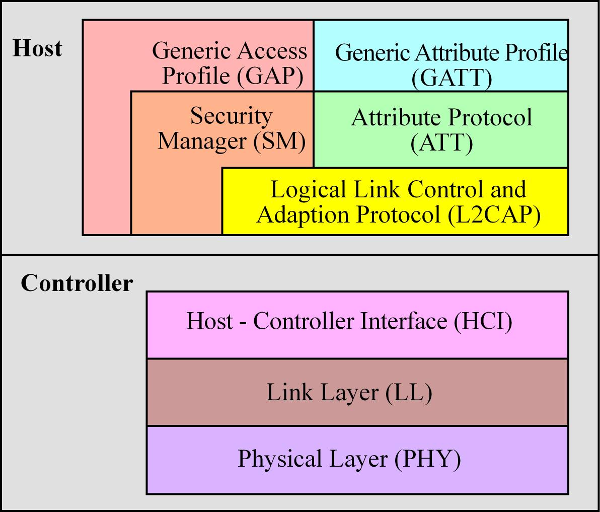
The BLE protocol stack includes a controller and a host. Layers
- The physical layer (PHY) is a 1Mbps adaptive frequency-hopping GFSK (Gaussian Frequency-Shift Keying) radio operating in the unlicensed 2.4 GHz
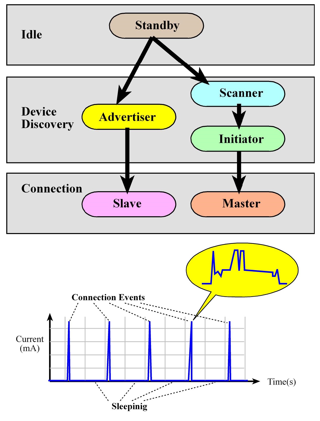
- The link layer (LL) controls the radiofrequency state of the device. The device states (5):
- standby: Initial state
- advertising: Transmit data without being in a connection, sending out periodic notifications of its existence and its willingness to connect
- scanning: Listening for advertisers
- initiating: Responding to an Advertiser with a connection request
- connected: if an Advertiser accepts a connection request, both the advertiser and initiator will enter a connected state. In this state a device will be connected in one of two roles master (client - device that initiated the connection) or slave (server - device that accepted the request)
- The Host Control Interface (HCI) layer provides a means of communication between the host and controller via a standardized interface, transports commands and events between the host and controller
- The Link Logical Control and Adaption Protocol (L2CAP) layer provides data encapsulation services to the upper layers, allowing for logical end-to-end communication of data
- The Security Manager (SM) layer defines the methods for pairing and key distribution, and provides functions for the other layers of the protocol stack to securely connect and exchange data with another device.
- The generic access protocol (GAP) layer handles the connection and security, for example thi layer is configured to setup and initiate advertisement
- The Attribute Protocol (ATT) layer protocol allows a device to expose “attributes” to other devices
- The Generic Attribute Profile (GATT) handles services and profiles and all data communications that occur between two devices in a BLE connection are handled through the GATT.
Connection flow
- A device configures and starts advertisement (E.g. BLE sensor)
- A device scanning for this notifications can request a connection becoming the initiator (E.g. smartphone).
- The advertisers accepts and both devices enter a connected phase (E.g. sensor=slave=server, smartphone=master=client)
- Once connected devices are mostly sleep to save power and the master (E.g. Smartphone=client) sends out
periodic requests to start communication. If the slave (E.g. sensor=server) has data to communicate, the master and slave will exchange data during this connection event
The client-server paradigm is the dominant communication pattern for network protocols. The client can request information from the server, or the client can send data to the server.
In BLE client-server read-write-notify operations
- When the client wishes to know the value of a characteristic, it will issue a read indication that contains a universally unique identifier (UUID) that specifies which characteristic is desired. The server will respond with the value by returning a read confirmation.
- When the client wishes to set the value of a characteristic, it will issue a write indication that includes data and the UUID that specifies to which characteristic the data should be written. The server will respond with an acknowledgement, called a write confirmation.
- When the client wishes to be notified about data on a certain value in the server, it will issue a notify request that only includes the UUID, the server will respond with an acknowledgement, and then the server will stream data. This streaming could occur periodically, or it could occur whenever the value changes.
BLE Devices:
- A peripheral device usually has sensors and actuators. On startup it advertises as connectable, and once connected it acts as a slave (E.g. an BLE controller Fan)
- A central device has intelligence to manage the system. On startup it scans for advertisements and initiates connections (E.g. A smartphone)
- A broadcaster has sensors collecting information that is generally relevant. On startup it advertises but is not connectable. Other devices can read this information even though they cannot connect to the broadcaster. (E.g. A thermometer)
- An observer can scan for advertisements but cannot initiate a connection. (E.g. temperature display for the thermometer)
Embedded IoT Communication Protocols
- TCP is a connection oriented protocol, which means the server, or a client, will open a socket and establish a connection with the server.
And the communication is done over a connection. For the duration of the communication, the connection is on. HTTP is based on TCP, this besides many other reason make
HTTP a bloated procotol, usually too heavy for embedded devices so other more lightweighted protocols were created like CoAP and MQTT
IoT Protocols
CoAP
- The Constrained Application Protocol (CoAP) was specifically developed to allow resource-constrained devices to communicate over the Internet using UDP instead of TCP, It's a one-to-one protocol.
- CoAP is particularly useful for communicating with low-power sensors and devices that need to be controlled via the Internet. Since we can interact with them using a traditional REST based API like HTTP
- CoAP is a simple request/response protocol very similar to HTTP, that follows a traditional client/server model. Clients can make GET, PUT, POST, and DELETE requests to resources.
- COAP works on UDP, it's connectionless with messages that fit into one UDP datagram (no fragmentation) and allows disconnected operation, which means that the client and the server are not connected to each other. therefore, they can act asynchronously.
MQTT
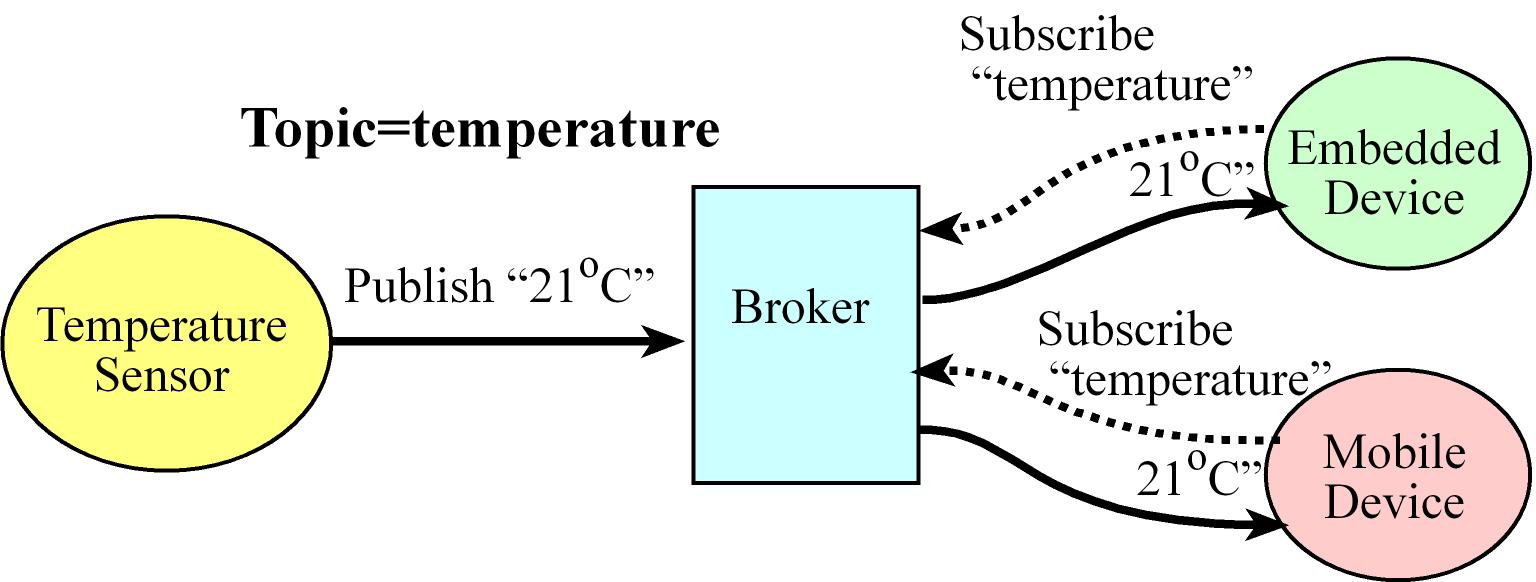
- The Message Queue Telemetry Transport (MQTT) is a publish-subscribe messaging protocol, it has a lightweight packet structure designed to conserve both memory usage and power
- MQTT uses an intermediary, which is called a MQTT broker, there are clients, or publishers, which produce data (this data is called topic in MQTT) with a unique identifier
- A connected device subscribes to a topic hosted on a MQTT broker. Every time another device or service publishes data to a topic, all of the devices subscribed to it will automatically get the updated information (the broker serves the subscribers)
TI CC2650
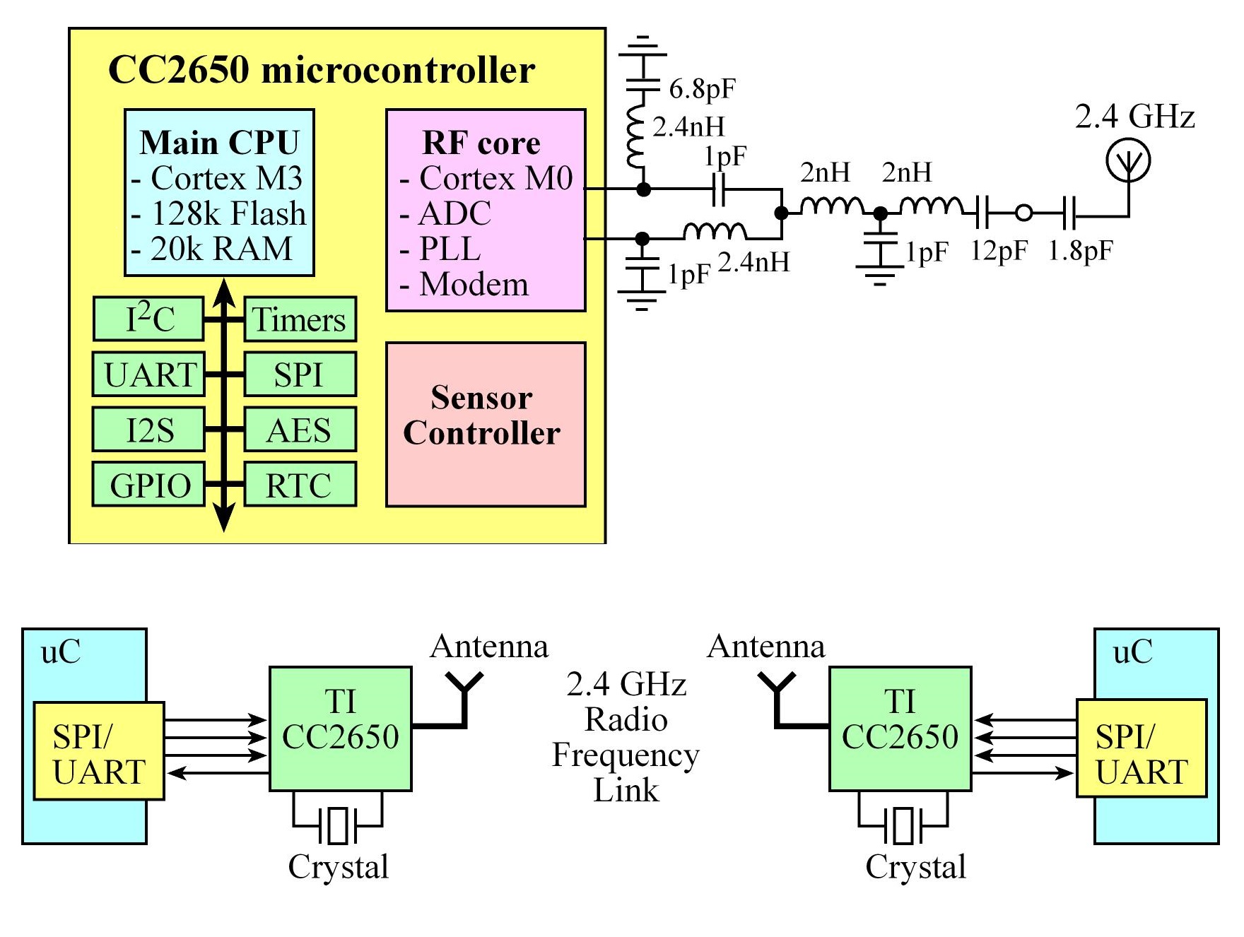
There are three controllers on the CC2650:
- Main CPU: Cortex-M3 128kB of flash, 20kB of SRAM, and a full range of peripherals, this runs the BLE stack and could also run the application code to single chip solution
- RF core: The RF Core contains an ARM Cortex-M0 processor that interfaces the analog RF and base-band circuitries,
handles data to and from the system side, and assembles the information bits in a given packet structure.
Offers a high level, command-based API to the main CPU, it is capable of autonomously handling the time-critical aspects of the radio protocols
- Sensor controller: Provides additional flexibility by allowing autonomous data acquisition and control independent of the main CPU,
The CC2650 BoosterPack comes preprogrammed with the simple network processor described in the next section. With a JTAG debugger, other programs can be loaded onto this CC2650. allowing for a single chip solutions using BLE
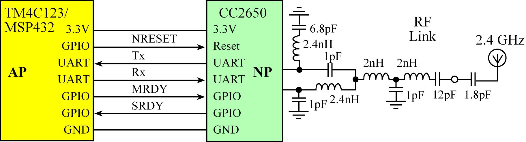
CC2650 Network Processor Interface and Process flow
- Simple Network Processor (SNP) is TI's name for the application that runs on the CC2650 when using the CC2650 with another
microcontroller, the controller and host are implemented together on the CC2650 and the profiles and application are implemented
on an external MCU. Using a UART and some GPIOs to communicate with the CC2650
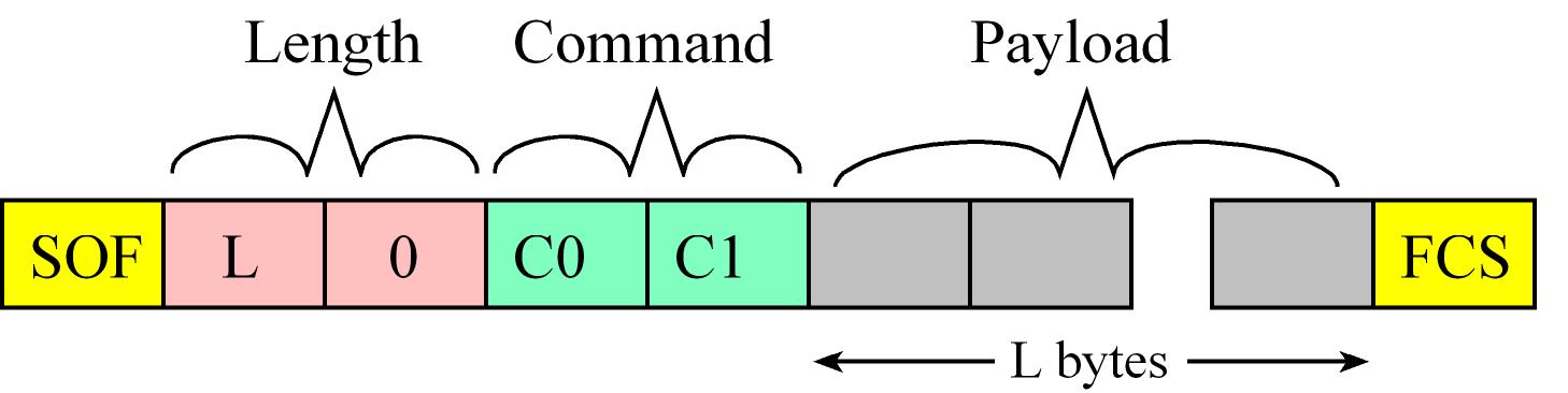
- Messages Format between the external MCU (AP - master) and CC2650 (NP - slave):
- First byte is the start of frame (SOF) =
254 (0xFE)
- The next two bytes are the Payload Length (L) in little endian format
- The fourth and fifth bytes are the Command
- Followign bytes are the command Payload in case it has, it contains the parameters of the command
- Messages end with a Frame Check Sequence (FCS)
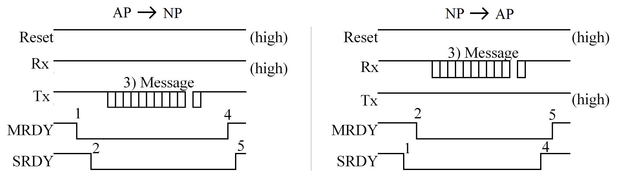
- Messages between the external MCU and CC2650 can be sent from AP (master) to NP (slave), or vice versa
- AP -> NP:
- AP sets
MRDY low
- Wait for NP to respond with
SRDY low
- AP sends UART message
- AP pulls
MRDY high
- Wait for NP to pull
SRDY high signaling ack
- NP -> AP:
- NP sets
SRDY low
- Wait for AP to respond with
MRDY low
- NP sends UART message
- NP pulls
SRDY high
- Wait for AP to pull
MRDY high signaling ack
- Network Processor (NP) Config and Data Flow
- Application microcontroller (AP) resets the CC2650 (NP) by setting
MRDY high and pulses reset low for 10 ms
- After the CC2650 reset, the next step is to create services and characteristics.
- To create a service, the master first issues an Add Service command (0x35,0x81). For each characteristic, the master sends an Add Characteristic Value (0x35,0x82) and an Add Characteristic Description (0x35,0x83) message
- Once all the characteristics are defined, the master sends a Register Service command (0x35,0x84).
- After services and characteristics definition the master will setup and initiate advertising by sending 4 commands: A set the device message (0x35,0x85), two set advertisement messages 1 (0x55,0x43) to configure the parameters of the advertising and finally a start advertising message (0x55,0x42)
- After the devices are connected the client can issue read-write
- a read request (E.g. smartphone asking for data from sensor) which will cause the NP sends a read indication to the AP, the AP should responds with a read confirmation containing status, connection, handle (UUID), and the data which will be send to the client
- a write request (E.g. smartphone setting data to sensor) which will cause The NP sends a write indication to the AP with the data to be written, the AP should respond with a write confirmation containing status, connection, handle (UUID) which will be send to the client
Each of the commands has an acknowledgement response.
References
