CS8803: Introduction to Operating Systems
Operating Systems Overview
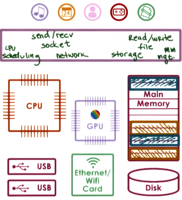
An OS is a special piece of software that abstracts (the HW usage and interaction) and arbitrates (manage/oversee HW use) the use of a computer system
- An OS has different abstraction and arbitration mechanisms for the various types of HW in a computer system
The OS manages the HW on behalf of the applications
OS main operations:
- Controls operational resources: use of CPU, memory, peripherals, etc.
- Enforce policies like fair access to resources, limits resource usage, etc
- Abstract HW complexity through system calls
- Provides isolation and protection for multi-running application systems
OS elements
- Abstractions: refers to the underlying resources. For example
file, socket and memory page (which correspond to HW resources the OS manages) or process and thread (which correspond to actual application the OS execute)
- Mechanisms: define how to operate with the defined abstractions. For example
create and schedule (which are used to launch or execute applications) or open, read, write and allocate (used to interact with HW abstractions)
- Policies: define how the mechanism will be used to manage the abstractions (the HW). For example Least-Recently Used (LRU) memory management, defines maximum limit of opened files per process, Round-robin,
System Calls
Interaction between application running in user-mode and OS running in kernel model is done through system calls to request services from the OS and signals to pass OS notifications into the applications
System Call general flow:
- Write Arguments
- Save relevant data at a defined location
- make the system call
System calls can be synchronous (wait until the system call completes) or asynchronous
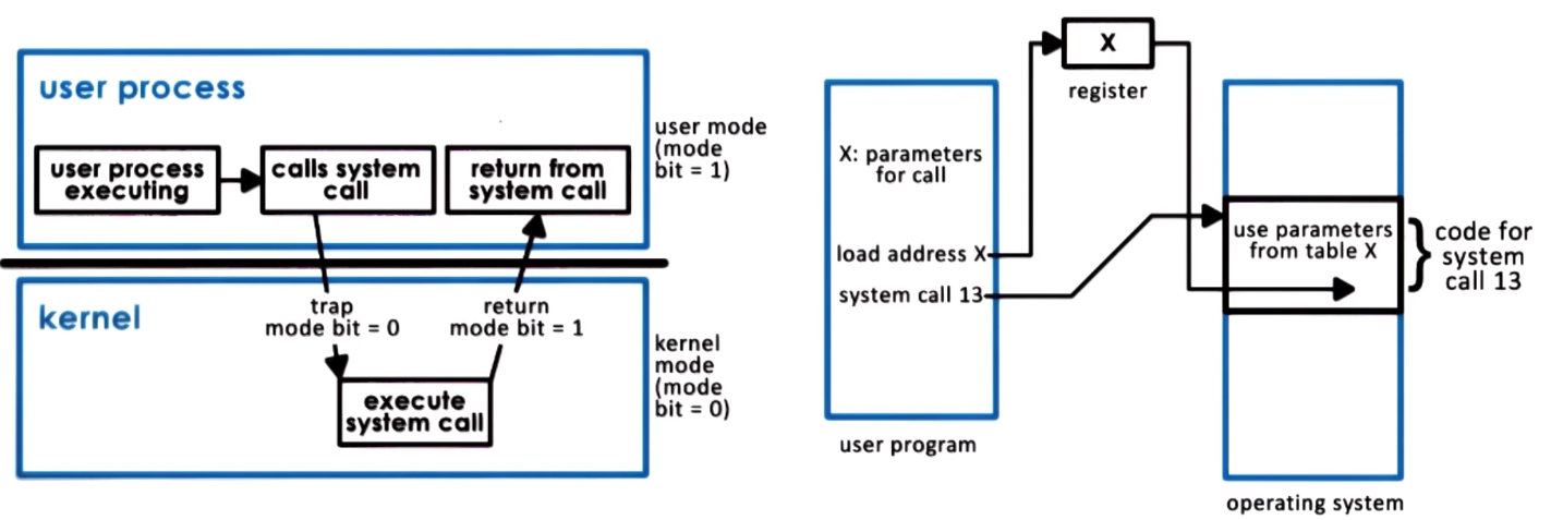
User to kernel transitions cause overhead due to switches in memory locality and cache, kernel code execution, etc.
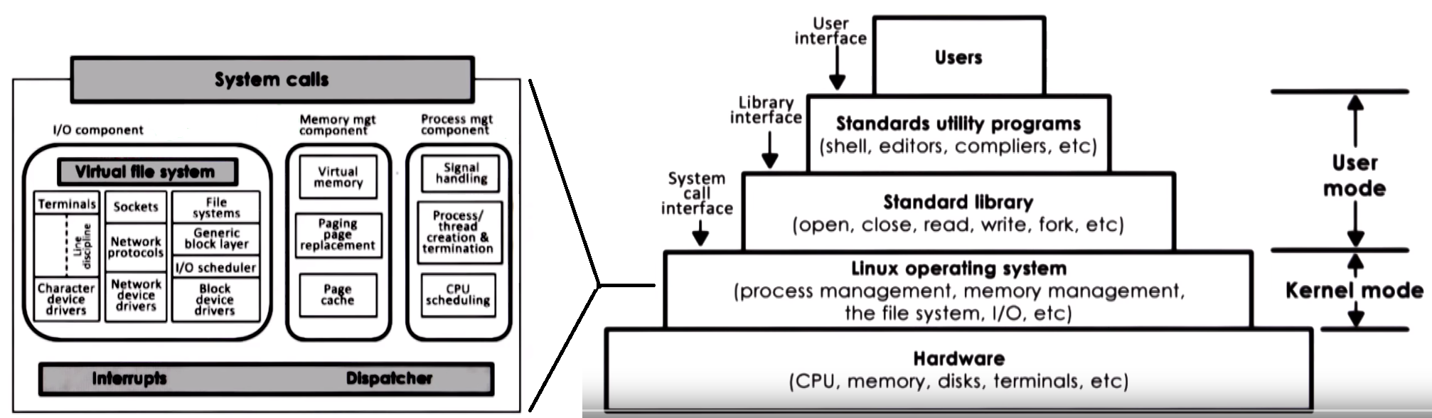
- An OS provides HW access through services which are accessed via system calls, there can be low level services (scheduler, memory manager, block device driver) or high level services (file system services)
- OS organization
- Monolithic OS
- Modular OS
- Microkernel
Processes and Process Management
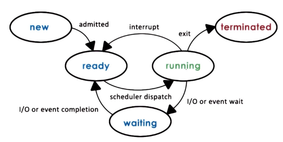
A process is an instance of an executing program, it represents the execution state of an active application
- A process may not be actually running, it maybe waiting for the CPU, user input or some IO device
- task or job are usually used as synonyms of process
An application is stored on some memory as a static entity when is loaded in memory and executed it becomes an active entity or a process
Process properties:
- State of execution: Program counter, stack
- Data and Register state
- State in memory
- May require I/O and HW
A process address space is an OS abstraction used to encapsulate all of the process state which includes stack, heap, data (variables) and text (code)
data (variables) and text (code) are a type of static state (available since the process loads)stack and heap, are dynamic state since the process creates them during execution- A process encapsulates stack, heap, data and text for a running application
process address space refers to the virtual address space used by a process to store its state
- virtual because they don't have to correspond to actual physical addresses in physical memory
- process address space fully represents a process
The memory management HW and operating system memory components responsible for memory management, like page tables, maintain a mapping between virtual and physical addresses
The OS dynamically decides which portion of which address space will be present where in physical memory, processes may have some portions of their address space not present in main memory but temporarily swaped on disk
The OS makes process think they have access to all memory so even if two process are running at the same time the virtual address space ranges may/will be the same for example from 0 to 64Kb but mapped to different physical addresses
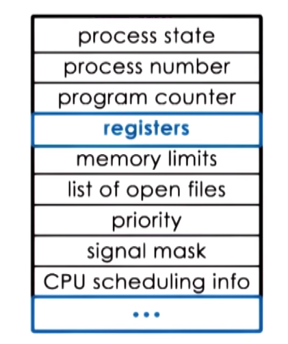
- PCB (Process Control Block)
- Data structure that the OS maintains for each of the process that it manages
- Created and initialized when a process is created
- It holds the execution context which is context information (
PC, CPU registers, SP, memory limits and mapping information, scheduling info and priority etc.) about a process
- Context switch refers to the mechanims used by the OS to switch execution from the context of one process to the context of another
Process life cycle and Creation
A process can create child process and in general all processes will come from a single root process, some process are priviliged process or root process.
In general how this works is tha once the boot process is done and the OS is loaded, the OS will create a number of initial processes,
then when a user logs in a user shell process is created then the user can create other processes from there for exampling when executing commands
A process can create a child process through the fork and exec mechanisms:
fork: copies the parent PCB into the new child PCB and child continues execution at instruction after the forkexec: Takes PCB structure already created and replace values for a new program
When you execute a program the OS actually is doing a fork followed by an exec, the fork is used to create a process PCB block and the the exec replaces the child image with the image of the new program
in the original UNIX based systems init is considered the parent of all process so all processes can be trace back to it
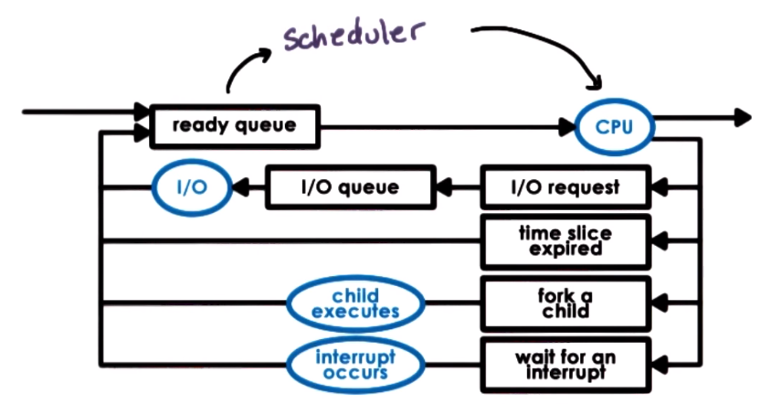
The scheduler is an OS component tha manages how processes use the CPU resources and decides which of the ready process
will be run by the CPU and how long it should run for. General scheduler process:
- preempt - interrupt and save current context
- schedule - run scheduling algorithm to choose next process to run
- dispatch - loads context and run the process on the CPU
Threads and Concurrency
For a process to use a multi-core system it needs to have multiple execution contexts it needs to have multiple execution contexts, these individual execution context are called threads
A multi-thread process is a single process with many execution contexts (Threads)
Threads
- It is an active entity, they execute a unit of work on behalf of a process
- They can work simultaneously with other threads (each on every core)
- They require coordination to access shared of resources (IO, CPUs, memory)
- They are part of the same address space of a process so they share all the code, data, files but could acces different portions of the address space
Thread can speed up execution due to
- Parallization by processing different parts of a chunk of data
- Specialization by executing diffent portions of the program, for example one thread for input/output operations, other for displaying, etc.
- Specialization also contributes to avoid cache performance issues because if thread only focus on a speciliazed set of operations there is a higher chance
that data needed will be actually present in the cache
In a multi-threaded process the PCB needs to hold separate information about every thread (specifically it needs
each of the execution contexts) that is part of that process
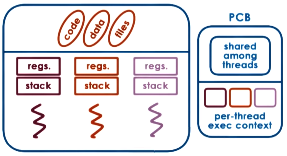
Threads share address space! because of this thread communications are implemented via shared variables in the same address space they are more efficient
than interprocess communication and since we dont need to allocate address space for each thread they are more memory efficient as well
Thread can be useful when # threads > # CPUs or even in single CPU systems if for example the idle time of thread is much greater than the context switch time (t_idle > 2*t_ctx_switch)
- Context switch between threads is usually much smaller that context switch between processes
- Multithreading helps us to hide or minimize I/O idle times, in other words hide I/O latency
- Threads can also help OS kernel by multithreading we allow the OS to support multiple execution contexts, threads can execute Kernel device drivers routines
When process execute they each operate within their own address space while threasd share the same virtual-to-physical address mappings
A common paradigm in multi-threaded applications is to have a parent thread that only creates other threads and waits until they finish
Synchronization mechanisms, Concurrency Control & Coordination
- Mutual exclusion is a mechanism that ensures only one thread at a time is allowed to perform an operation and it can be implemented with a mutex
- Using condition variables to wait on other threads specific condition before proceeding execution
- Deadlock two or more competing threads are waiting on each other to complete which results in none of them ever run
(threads get stuck in a cycle of waiting), to avoid this we can maintain lock orgder when locking different resources or have master lock for multiple resources
- A race condition happnes whenb two or more threads try to access a shared resource (data, variable, IO device, etc.) without any synchronization,
happens when one htread is trying to access or modify a resource that other thread is also accessing/modifying
Multithreaded Patterns
- Boss-Workers: One boss thread that assigns work to one or more worker threads, worker perform job and report back to boss, to
assign work the boss usually uses a producer/consumer queue. In this scenrario a pool of workers exists at initilization and in case the
queue gets full the boss can increase the pool of workes dynamically to try to improve throughput. As a variant of this model
instead of having general workers there could be specialized workers for certain jobs
- Pipeline: Application is break down to multiple stages and each thread is assigned to a stage, so the entire application task is executed as a pipeline of threads,
in this approach multiple threas are executing concurrently working in different pipeline stages, ideal if each stage in the pipeline takes the
same amount of time because the general throughput depends on the weakest/slowest stage, we can improve this by having a dynamical
pool of threads for each stage that grows accordingly, instead of a single thread per stage, communication between stages can be implemented using producer/consumer queues
- Layered: groups related subtask in a layer and then multiple layers work together to solve the whole problem
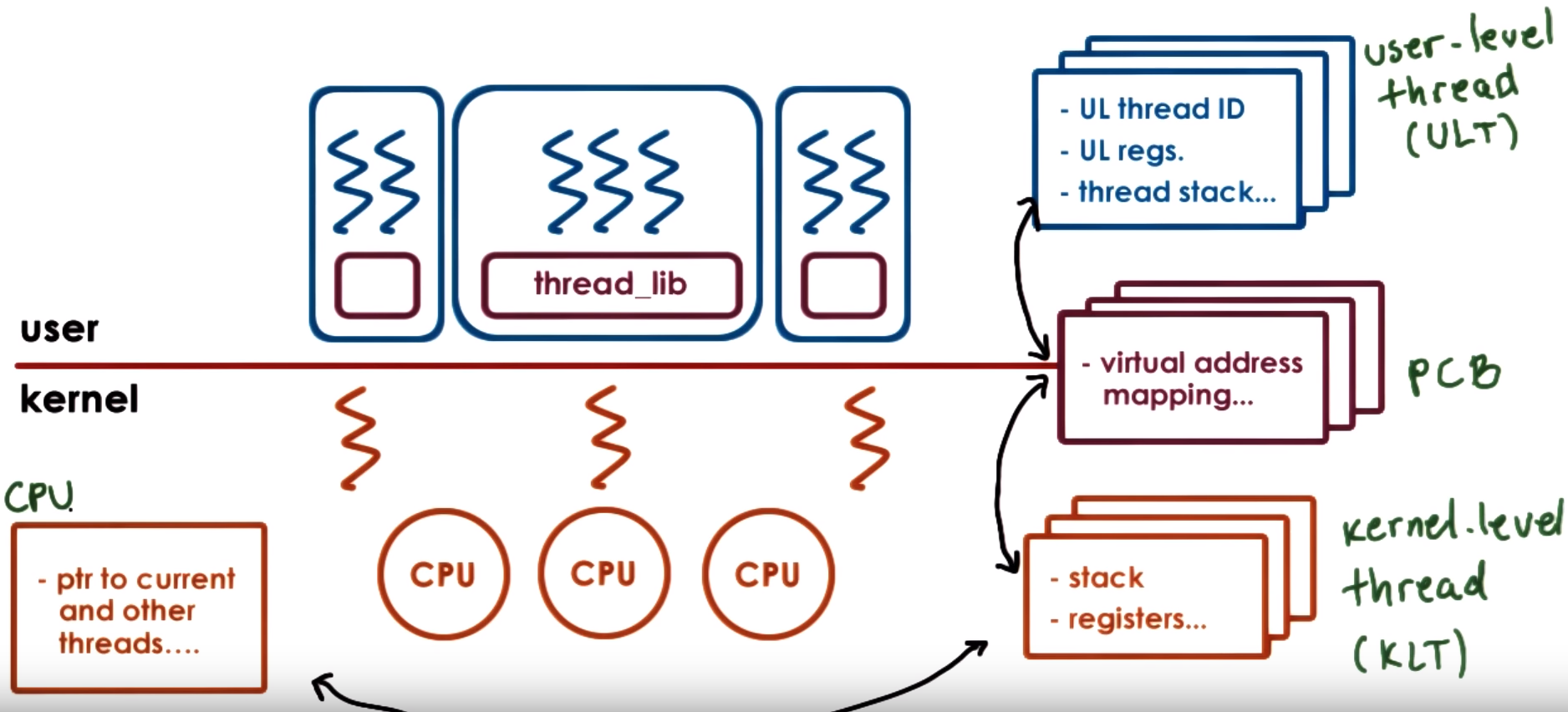
Kernel-level vs User-level threads
Supporting threads at the kernel level means the OS kernel is multi-threaded and performs scheduling and synchronization operaions
to allow these kernel threads to share resources
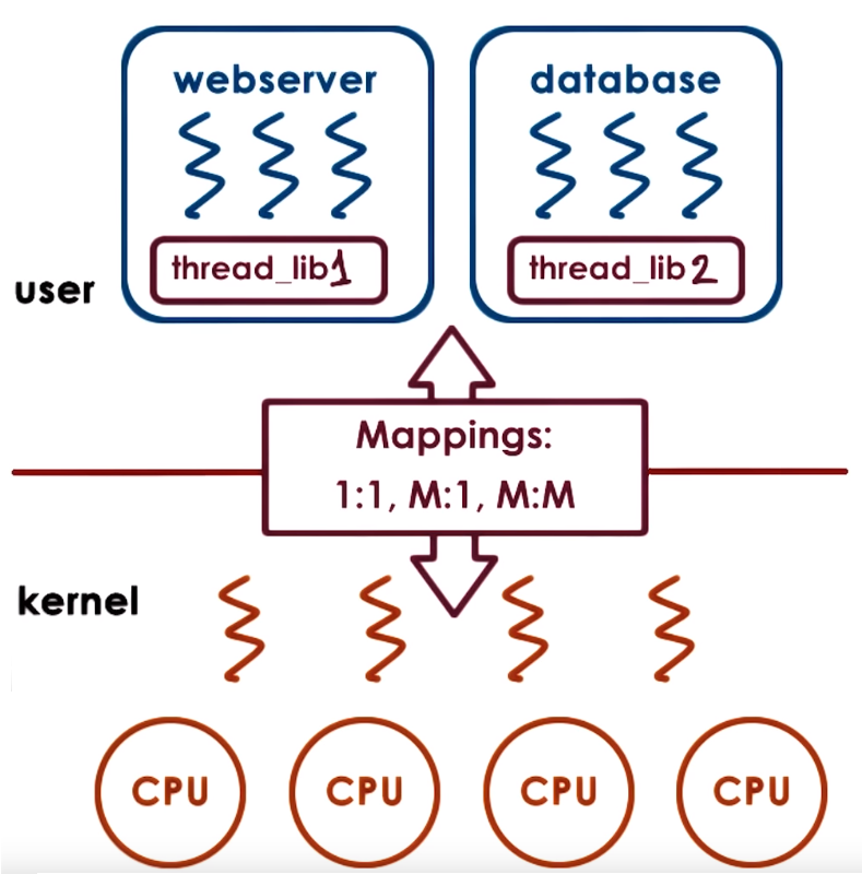
Supporting threads at the user level means there is a user-level library that is linked with the application and provides all
the management and runtime support for threads, the library provides scheduling and sync synchronization
For a user level thread to be executed it first needs to be associated with a kernel level thread so first the OS scheduler
schedules that kernel level thread onto the CPU that will end up executing the user level thread. Association models between kernel and user threads:
- One-to-One Model - 1:1: Each user level thread has a kernel level thread associated
- Many-to-One Model - M:1: Many user level threads have a single a kernel level thread associated
- Many-to-Many Model - M:M: Allows some user level threads to be associated with a single a kernel level thread and also allows other user level threads to have a one-to-one mapping with other kernel level threads
The User level thread library decides which user-level thread will be scheduled onto the underlying kernel level threads
The User level threads managed by the user-level threading library tracks all the user-level threads that represent a single process
The process control block - pcb that represents the address space needs to keep a relationship between user level threads and kernel level threads
because for each process we need to keep track of what are the kernel-level threads that execute on behalf of this process
When the kernel needs to schedule or context switch among kernel-level threads that belong to different processes it needs to determine
they point to a different PCB to restore the entire PCB
Adaptive mutexes refer to mutexes that can become blocking or spining mutexes deoending on the situation for example spin for
short critical sections and block for long critical sections
The information contained in the PCB is divided
- Hard process state: related to all user level thread that execute within that process
- Light process state: relevante to one (or a subset of) user level thread that are associated with a particular kernel level thread
kthread_worker defined in include/linux/kthread.h can be considered the kernel thread structure in linux, it provides a simple interface
for creating and stopping kernel threads and within this the task_struct is used to describe the process the kernel thred is running and system needs at least
20 threads to boot the system, it could be more and the value is stored in max_threads
- The kernel level thread and user level thread library interact through a series of system calls and signals which allow them to coordinate
PThreads
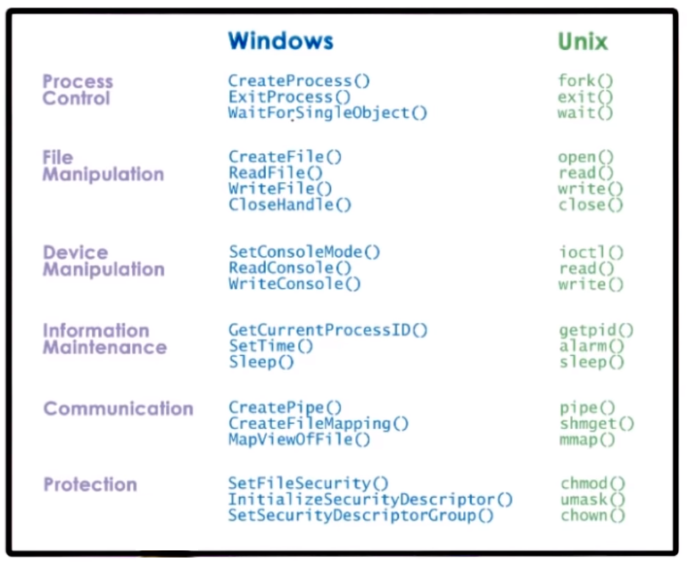
POSIX (Portable Operating System Interface) - is a standard that describes the system call interface that operating systems
need to support to be compliant with this standard which intents to increase interoperability among OSs
PThreads == POSIX Threads. Pthreads is a part of the POSIX standard that describes the API an OS needs to support in
order to create, use and manage threads, this includes threads and synchronization and coordination constructs like mutexes
A pthread_t is joinable by default which means a parent can create children threads and must be joined to the parent (parent must wait for them to finish)
otherwise it can create "zombie" threads. We can also set an attribute so a pthread can be detachable in this case parent created tchildren threds but this can not be joined
PThreads API provides the pthread_mutex_t mutex structure that supports lock, unlock and trylock (check mutex if free lock if not free do not block just notify of this) operations
PThreads API also provides the pthread_cond_t data structure that represents a condition variable and supports wait, signal and broadcast operations
During init calls to pthread_t, pthread_mutex_t and pthread_cond_t we can provide data structures with different attributes, using pthread_attr_t, pthread_mutexattr_t and pthread_condattr_t, to specify threads ans mutexes behavior
You must init (use init struct macros or the init functions) and destroy pthread_mutex_t mutexes and pthread_cond_t condition variables
pthread_setconcurrencysets the concurrency level, in other words informs the application's desired concurrency level, a value of 0 instructs to manage concurrency as it deems approriate
Interrupts ans Signals
Interrupts asynchronous events generated by external components (like I/O devices, timers, other CPUs), they represent some type of
notification to the CPU that some external event has ocurred, the interrupts are determined by the system/platform (architecture and HW in general)
- In some systems Interrupts are carried directly through wires conneced to the CPU but in modern systems they are carried through special messages,
Message Signal Interrupt (MSI) that can be carried on the same interconnect that connects devices to the CPU complex PCIe for example
- For all the interrupts supported by the system there is table that specifies the handler for the specified interrupt which will execute
in the context of the thread that was interrupted
Signals are events triggered by the software running on the CPU, signals depend on the OS or running software in general, they can be synchronous
(occur in response to specific action took by the CPU) and asynchronous
- While running some code the OS can generate a signal related to something that was being executed and then a handler to this signal is executed,
there are default action/handlers for signals but the handler can also be specified by the process using special system calls like
signals() and sigaction().
- For example if some code is trying to access illegal memory, the OS signals a SIGEGV signal and a default action like terminating the process
is executed if an specific handler is not specified
- Types of signals:
- One-Shot Signals - override behavior: the handler is executed once unregarding of how many signals were received, for example it doesnt matter if
n
signals are pending or just one the handler will be executed only once then the signal is disabled so the handler does not execute again,
if it is needed it can be renabled to execute the handler again once one or mutiple signals are detected
- Real-Time Signals - accumulate behavior: The handler is execute for every signal raised, so if
n signals are received, the handler is called n times
Interrupts and Signals:
- They have an unique ID that depend on the HW (in the case of interrupts) or on the OS (in the case of signals)
- They can be masked/disables/suspended it can be masked per CPU (for interrupts HW routing mechanims will not deliver interrupt to CPU), per process (for signals kernel wont interrupt corresponding thread)
- Signals and interrupts can be executed in the context of the thread that was interrupted (using its registers and stack) or as a separate thread this depends on the OS kernel implementation and usually a combination of both is used E.g. Linux use top and bottom half approach
- When enabled triggering them results in invoking a handler
- Interrupt handler are set for the entire system by the OS
- For Signal handlers the OS allows processes to specify their per process handling operations
Masking interrupts can be useful to avoid threads being interrupted on critical sections (which can cause issues like deadlock),
but masking can also cause pending interrupts to accumulate while being masked which could cause only one interrupt to be handled
On muticore systems interrupts can be directed to any CPU that has them enabled but we can specify only one CPU will handle interrupts
Two identical platforms will have the same interrupts but different signals can occur depending on the OS that is running (or SW in general that is running)
- In Linux interrupts are divided into:
- top-half: fast, non-blocking, requires min amount of processing and it executes immediately when interrupt occurs to handle critical processing
- bottom-half: can have arbitrary complexity, can block and it can execute later as a separate thread only restricted by maybe specifics of the interrupt being handled like for example IO device timeouts
Linux Tasks
The abstraction to represent an execution context is called a task and in code is described in the task_struct in Linux,
it represents the execution context of a kernel level thread (KLT)
A single threaded process will have 1 task and a multithreaded will have many tasks,
The pid_t pid; field in this task struct is actually the thread identifier (this is due to historic reasons)
but if we have a single threaded process the task/thread ID and process ID are the same, in a multithreaded process the process ID
and the first task/thread that was created when the process was first created have the same ID which is also stored in the task group ID tgid (= process ID).
The task_struct has a linked list of tasks that are part of the process through the list_head tasks; field
To create a new task Linux support the clone operation that can share everything or some parts of the parent thread by using thr sharing_flags argument,
fork is internally implemented via clone (fork is just a special case of a clone call). The main use of clone is to implement threads,
multiple threads of control in a program that run concurrently in a shared memory space.
Linux Threads is called Native POSIX Threads Library (NPTL) that supports a 1:1 model so there is a kernel levekl task for each user level thread.
With this model Kernel sees all user-level thread info
Paradigms for Concurrency / Concurrent Applications Paradigms
Scheduling
- A Scheduler is like a manager that schedules work, it decies how and when process (and their threads) access the CPU(s)
- Usually the same scheduler is used to schedule user-level threads and kernel level threads
- The scheduler looks through the tasks in the ready queue and chooses one to run on a CPU, giving it some amount of time to run (timeslice)
- the timeslice is the maximum amount of uninterrupted time given to a task, the task may run less than the timeslice (in case it finishes early, has to wait on IO, blocks due to synchronization, etc.)
- The scheduler runs when a CPU becomes idle (due to IO request or other wait operation) or when a time slice has expired
Types of Scheduling
- Non-Preemptive or Run-to-Completion Scheduling: Assumes when a task is assigned to a CPU it is run to completion (not preempted)
- Preemptive Scheduling: Task can be interrupted before finishing
- Round-Robin: cycle through task giving them a fixed timeslice and preempt them if their time slice expire or if they yield execution.
This approach make short tasks finish sooner, more responsive due to interleaving tasks, lengthy IO operations can start sooner
Scheduling metrics
Throughput = jobs_completed / time_to_complete_all_jobAvg. Completion Time = sum_of_times_to_complete_each_job / jobs_completedAvg. Wait Time = (t1_wait_time + t2_wait_time + ... + tn_wait_time) / jobs_completed
CPU bound tasks prefer longer timeslices because with this we have less context switch overhead
IO bound tasks prefer short timeslices because with this IO operations can be issued earlier and gives a more responsive application
Scheduling Algorithms & Policies
The Scheduling Algorithm/Policy determines which task from the tasks that are ready to run should be selected with the
intention to Maximize Resources (CPU, devices, memory, etc):
First-Come First-Served (FCFS):
- Schedules tasks in order of arrival, so tasks are organized in a FIFO queue (add to end of queue, get from start of queue)
Shortest Job First (SJF):
- Schedules task in order of their execution time, so tasks are organized in an ordereded queue or tree, shortest task and the beginning
Priority:
- Tasks have different priority levels, so it schedules tasks in order of priority, tasks are organized in priority queues or priority tree
- starvation can occur in priority scheduling which refers to having a low priority task that never gets to run due to other higher priority tasks,
this can be solved with priority aging which means making the priority a function of the actual priority and also the time spent without being run (stuck in a run queue)
- priority inversion is a phenomenon that could happen when assigning priorities to task in which the priorities appear omverted due to higher priority
task needing to wait for resources (mutex) that lower priority tasks are using. This can be solved by boosting the priority of task that acquire the resources (mutex)
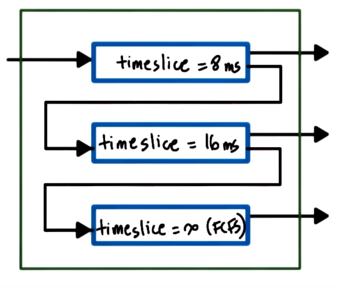
Multi-level Feedback Queue: Uses multiple priority queues. The higher priority tasks (placed on a high priority queue)
have the shorter timeslices and lower priority tasks have longer timeslices
- If a task yields before using all its time it remains on the same queue (this means it's more IO intensive and we made a good priority choice)
- If a task uses all its time (this means it's more CPU intensive) it is pushed to a lower priority queue (by doing this we update its priority)
- Tasks in lower priority queues can be boosted (pushed to higher priority queues) when releasing CPU voluntarily for example due to IO operations/waits
Linux Scheduler - Linux O(1)
The Linux O(1) Scheduler was introduced in kernel 2.5 and it is able to perform task management operations (like select to run, add task to be run, etc)
in constant time regarding of the total number of tasks in the system.
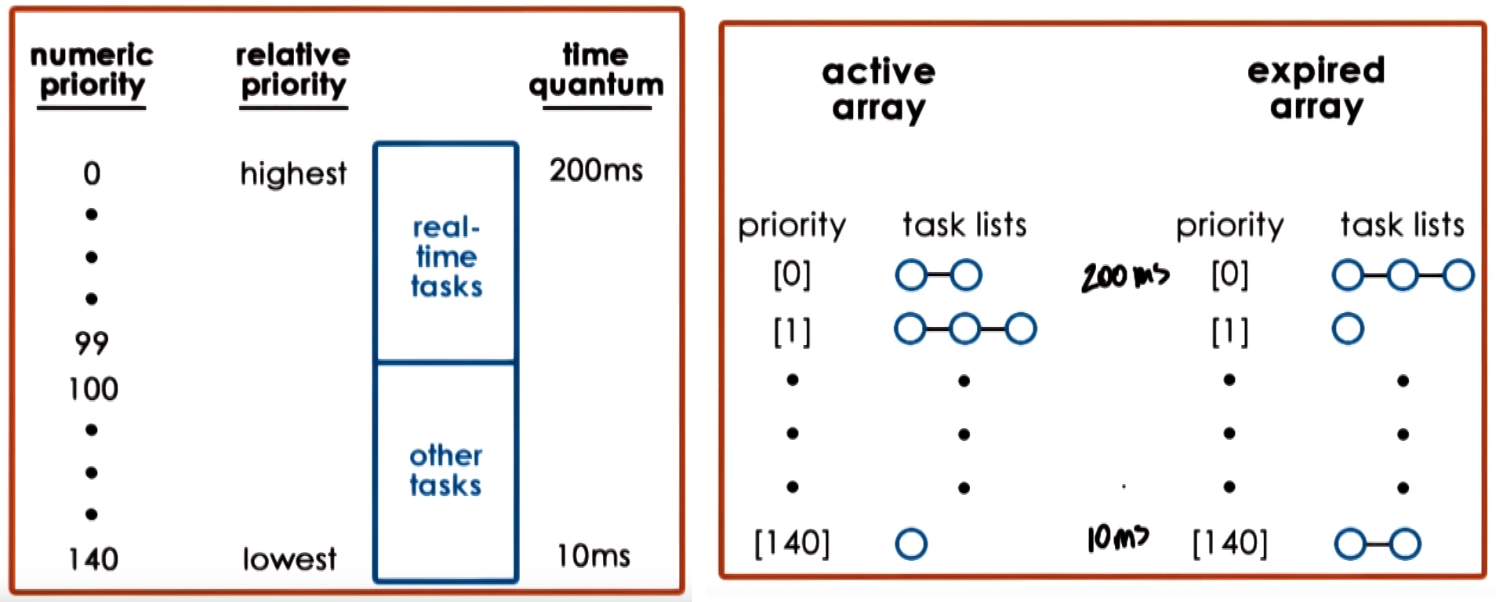
Linux O(1) is a preemptive and priority-based scheduler, with 140 priority levels from 0 (highest priority) to 139 (lowest priority)
- Real-time tasks (priority from
0 to 99):
- Timesharing tasks (priority from
100 to 139):
- User-processes have a default priority of
120 that can be adjusted with a modifer that goes from -20 to 19 (to result in priority between 100 and 139)
Linux O(1) associates different timeslice values with different priority levels and has a feedback loop that adjusts tasks priority
level based on how a task behaved in the past
- Assigns shorter timeslice to low priority tasks (CPU bound) and longer timeslice to high priority tasks (interactive)
- Considers sleep/wait time of task for priority changes:
- Longer time sleeping/waiting/idling means more interactive task (more time waiting for user), this gets increase in priority (a boost
priority-5) to get longer timeslice
- Shorter time sleeping/waiting/idling means more compute-intensive task, this gets lowered in priority (lowered
priority+5)
The structure to roganize the tasks consists of 2 arrays (Active & Expired), each element of each array points to the first element of a task list corresponding to the priority level
- Active:
- Primary lists of tasks that the scheduler uses to pick the next task to run
- Takes constant time to add/select tasks from the array due to special instructions and consideration
- Tasks are removed from the active array only if it consumes its entire timeslice and moved to the expired array (if it blocks due to IO waits only the time used is substracted and continues in active array)
- Expired:
- Contains lists of inactive tasks, these task wont be selectded as long as there are tasks in any of the lists in the active array
- When no more task are in the active array, the arrays (that contain pointers to lists) are swapped (the expired becomes active and actiuve becomes expired)
Linux Scheduler - Complete Fair Scheduler (CFS)
The Linux CFS was introduced in kernel 2.6.23 to replace the Linux O(1) due to fairness and jitter issues, it schedules non real-time task, the real-time tasks uses a real time scheduler
Uses a Red-Black Tree structure to organize tasks, tasks are ordered based on the amount of time spend on the CPU (vruntime),
nodes to the left represent tasks that had less time on the CPU (so need to be scheduled sooner) and nodes on the right represent taks that had more time on the CPU (so no need to be scheduled as quickly)
CFE always schedules leftmost node (task that had least amount of CPU time)
Periodically vruntime (in nanoseconds ns) of the task running on the CPU is incremented/adjusted by the scheduler and
at that point it compares the runtime of the currently executing task with the leftmost task in the tree
if current vruntime < leftmost vruntime continue running, if current vruntime > leftmost vruntime preempt and place accordingly in the tree.
In other words current task has run less than task in leftmost node in the tree keep running current task otherwise preempts,
place current task appropriately in the tree and run leftmost node
The periodic update of vruntime depends on the priority of the tasks
- Faster rate ->
vruntime increase faster for low priority tasks, this gives them less amount of CPU time
- Slow rate ->
vruntime increase slower for high priority tasks, this gives them more CPU time
Only uses one Red-Black Tree structure for all the priority levels and takes constant amount of time to select a
task but adding a task takes log time depending on the number of tasks in the systems, this is due to tree insertion
Scheduling on Multiprocessor
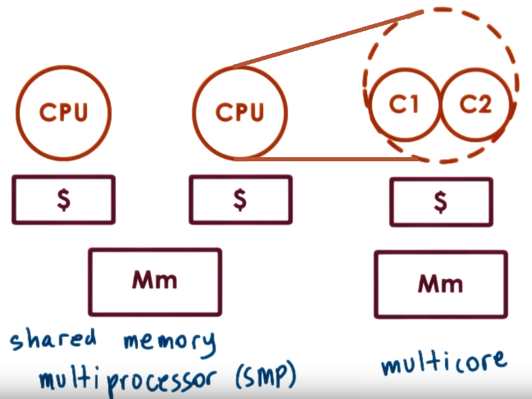
A scheduler sees each core as entities into which it can schedule an execution context (threads) so for the OS
each of the cores of a multi-core CPU or a core in a single-core CPU are all seen as "CPUs" where it can schedule some workload
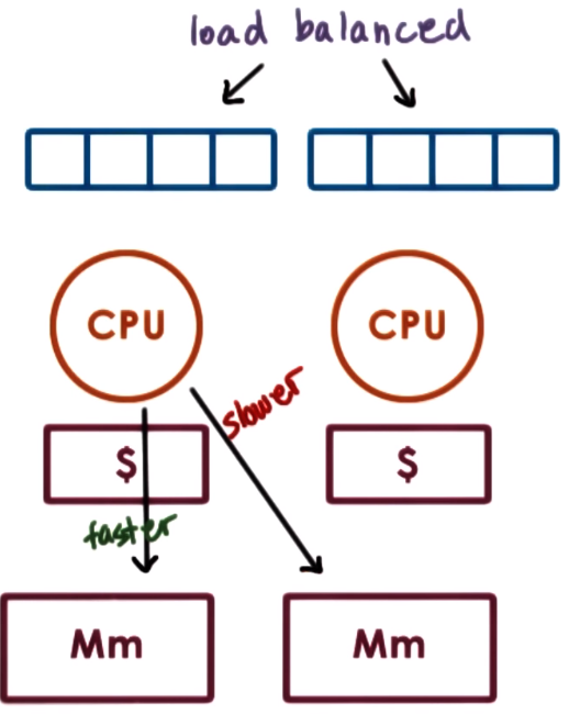
cache affinity reffers to trying to schedule the thread on the same CPU where it executed before because it is more likely
that is cache is hot (has the information needed by the thread), in other words keep task on the same CPU as much as possible.
This can be achieved by a load balancer that divides task among CPUs then having a per CPU scheduler repeatedly schedules those same tasks on the CPU
On Non-Uniform Memory Access (NUMA) Systems there can be multiple memory nodes (which are interconnected with some type like QuickPath Interconnect - QPI)
and some can be closer (faster to access) to a socket of multiple processors so an OS that is NUMA-aware would try to shcedules tasks on CPUs
that are closer to the memory nodes where ther state is
- Cache-Coherent (CC) refers to systems in which HW performs all necessary steps to make sure that caches are coherent (in sync). Basic coherency methods:
- Write-Invalidate (WI): if one CPU changes a value in one cache the HW will make sure to invalidate that value if present in other caches so future references to the value will cause cache miss which will trigger an access to memory which must have the updated value through other mechanis
- Write-Update (WU): if one CPU changes a value in one cache the HW will make sure to update the value in other cache if it is present
Scheduling in Simultaneous Multithreading
Hyperthreading or Simultaneous Multithreading (SMT) refers to hardware support for multiple execution contexts this means a CPU
with multiple sets of registers in which each set can hold an execution context, only one thread is executing a time but due to multiple register sets,
context switch between threads is fast, it is just a switch between using one set of registers to another set, save and restore is not needed as often
SMT systems can be used to hide memory instructions latency accesses by mixing CPU and memory bound tasks, to determine whether a
tasks is CPU or memory the OS scheduler can use HW counters (like cache misses counters, CPI counter) that estimate what kind of resources a task needs
memory instructions can take more than a single CPU instruction cycle, instruction may need to wait on some stage in the processor
pipeline but this means thread is NOT sleeping, so memory instructiosn may have higher CPI (cycles-per-instruction)
Memory Management
Memory is used to capture the state of processing actions, the Memory Management responsibilities/actions:
- Uses memory pages or segments which are sized containers
- Brings state of tasks to memory and remove it if no neccessary
- Optimize/reduce time to acces state in memory, for this it relies on HW support like TLBs - Translations Lookaside Buffers, caches and also on SW algorithms for page replacement or memory allocation
Processes sees virtual addresses that are translated to physical addrees where actual data is store, the range of virtual
addresses establishes the amount of virtual memory visible in the system and this can be much larger than the actual amount of physical memory
To manage memory the OS must be able to:
- Allocate refers to the mechanisms to allocate, replace (move between main phy memory and secondary storage) and track how memory is used (trask what parts are free in phy memory)
- Arbitrate refers to defining how memory is being accessed in valid way, address translation (virtual to phy to access data) and address validation (verify is a legal memory section for a process)
Because Physical memory is smaller that virtual memory, data needed in the virtual address space by a process may not be present
in the physical memory, it may be in a secondary storage, so the OS needs mechanisms to decide how to replace the contents on the physical memory.
replace mechanism refer to the mechanism that determine which content should be broought in from disk and which content should be stored on disk

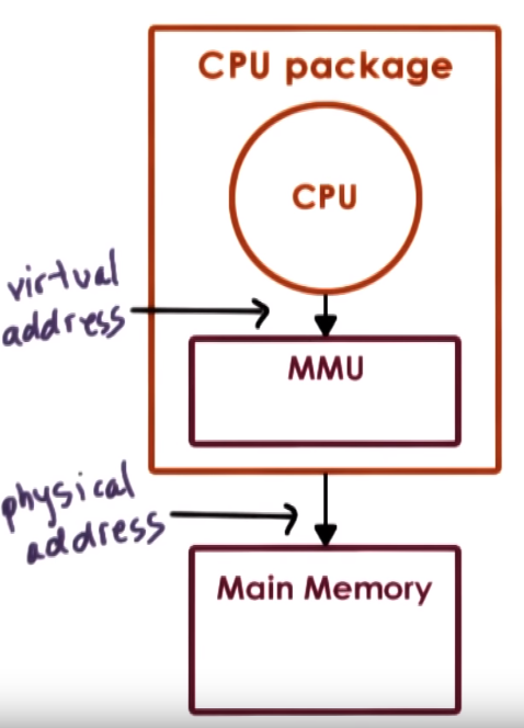
- Memory Management Hardware Support
- The Memomy Management Unit (MMU): Every CPU usually has an MMU which translates virtual addresses to physical addresses.
In other words the CPU issues virtual addresses and the MMU translates them to physical addresses. The MMU can report
a fault that signals an illegal access (address has not been allocated), invalid permission to perform a particular access or
that the page is not present in memory, the CPU place error code on kernel an usually a page fault handler is invoked which determines action based on the faulting error
- Translation Lookaside Buffer (TLB): MMU cache for the valid Virtual to Physical adddress translastions
- Designated registers that point to the currently active page table or base and limit size of a segment
- HW determines type of memory management support some HW support page-based, other support segment based or both
Virtual Address == Logical Address
Page-Based Memory Management
Virtual Address space is divided into fixed sized called pages, physical memory is divided into page frames of the same size,
so in terms of allocation the OS need to map pages to page frames and in terms of arbitration it uses page-tables
Virtual memory pages and physical memory pages frames are the same size
The OS memory management component is the one that decides which page frame are replace so it must update the page table accordingly
The OS creates a page table for every process that it runs so on a process context switch the OS needs to also switch to the corresponding table
The virtual Page Number (VPN) which is the first portion of the virtual address is used to index into the page table and the rest of the virtual address is the offset.
Combining this offset with the Physical Frame Number (PFN), which is stored in the location indexed by the VPN, results on the physical address
For each virtual address a page table entry is used to determine the actual physical location that corresponds to the virtual address
- The MMU relies on the page table entries to do the translation and enforce validity of the access
- The page table entry must contain the Physical Frame Number (PFN) and other flags that the OS and HW uses
- Present bit (P) field that the memory management used to determine status about the page for example if page is in memory
- Dirty bit (D) set if the page is written to, maybe needed to check if we need to update on disk
- Accessed bit (A) set if the page has been accessed in general (read or write)
- Protection bits (RWX) determine whether a page can be read-only, read-write

- The OS creates a page table for every process that it runs so on a process context switch the OS needs to also switch to the corresponding table,
due to HW support this usually mean changing/updating a register that is used to poin to the page table (E.g.
CR3 on x86)
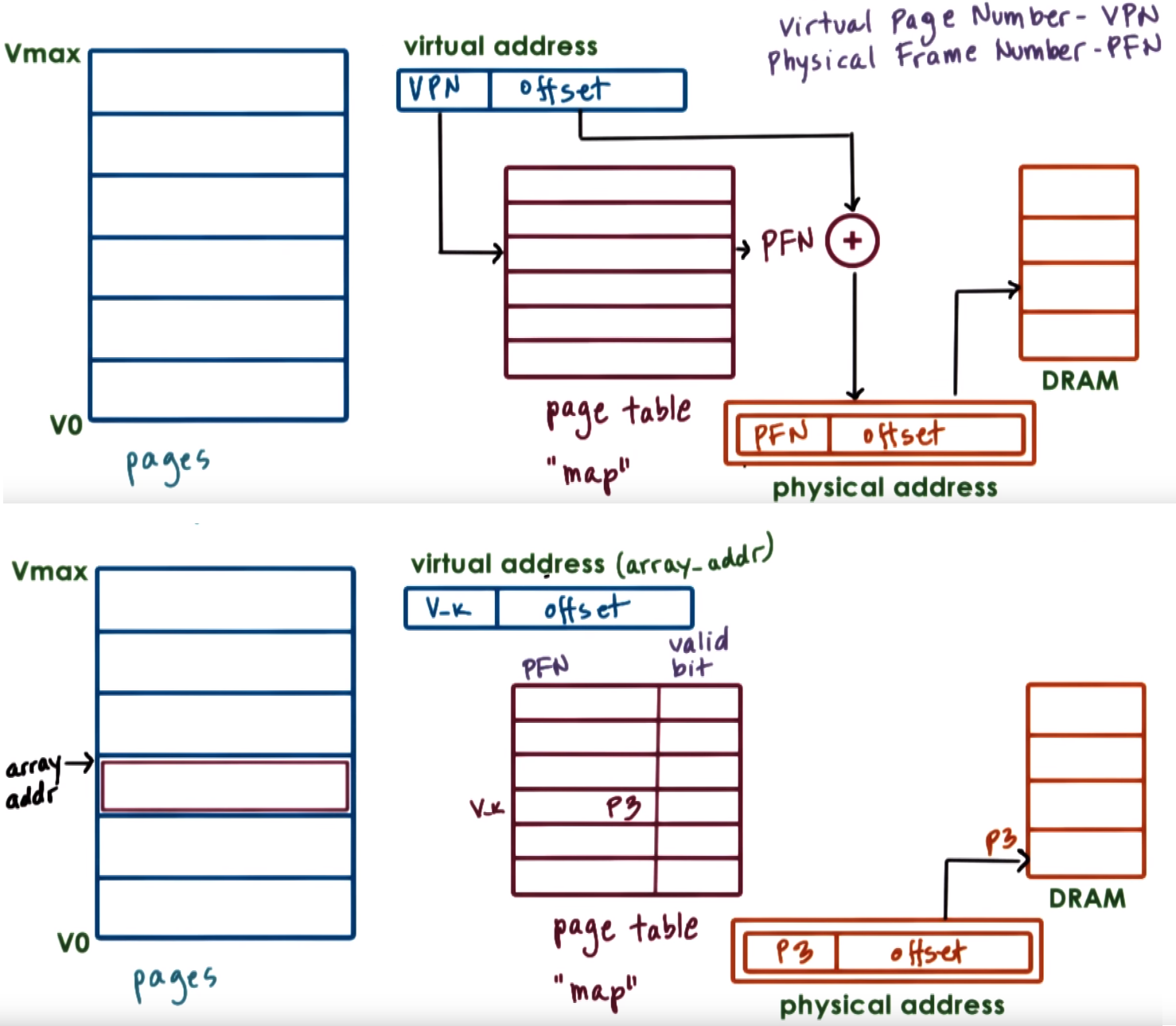
- Page-Based Memory Management Allocation & Access considerations
- We allocate memmory into the virtual address space of the process, this doesn't mean there is actual physical memory
that is storing this data, this ususally happens until we actually want to access this memory (read or write into it)
- The first time we access the memory the OS there is no physical memory that corresponds to this range of virtul memory so it allocates space on physical memory,
because memory was allocated until first access this is called Allocation on first touch
- If a process doesnt use its pages they probably will be reclaimed from physical memory (pushed to disk) and other content will take its place on memory
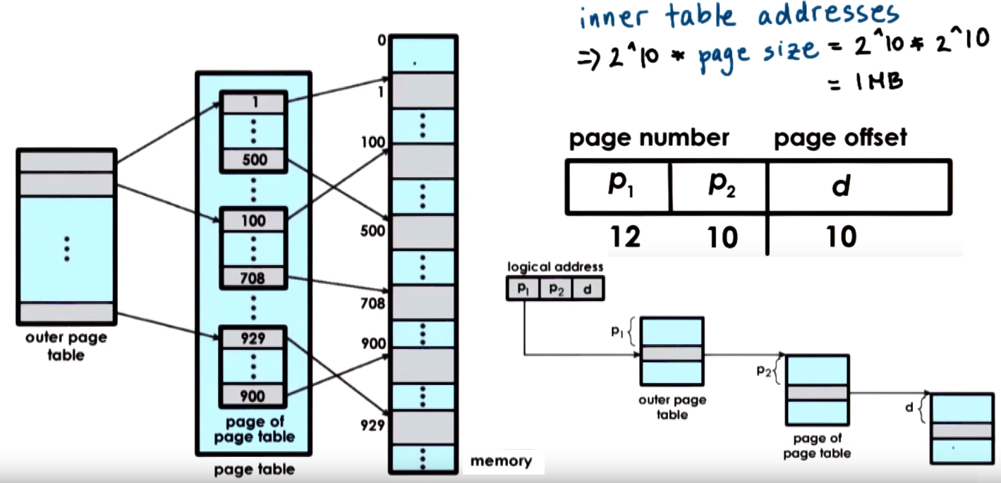
Multi-level Page tables
Page tables are designed in hierachical multi-level structure that consists of an top page table (outer page table) referred as the page table directory,
this doesnt store pointers to pages it store pointers to page tables, the internal page tables has page tables as its components that actually points
to pages, their entires have the PFNs and bit flags
The Internal page tables exist only for valid virtual memory regions
Holes in the virtual memory space will result in lack of internal page tables (which we DONT need to store in memory)
Additional layers can be added as we add more page directories and internal page tables end up covering smaller regions of the
virtual address space but require more more accesses (increased translation latency)
The offset field is the actual index into the actual physical page table and the offset size determines page size
- In Linux/x86 Page sizes:
4kB (default - 12-bits offset), 2MB (large - 21-bits offset), 1GB (huge - 30-bits offset)
- Larger page size results on smaller page tables (less entries) better performance of TLB bu if application
is not using all memory in page then memory is wasted
Page table size = (Size of Entry) + (Number of Page table Entries) and Number of Page table Entries = 2^(# VFN-bits)
- Example for a single level page table referencing 4GB (
32-bits) memory with page size of 4KB Offset = 12-bits then
Num of Page table entries = 2^(32-12) = 2^20 = 1M and Page Table Size = (4 Bytes)*(1M) = 4MB
Number of acceses:
- On single-level page table for each memory reference there are 2 accesses to memory 1 for access to page table and 1 access to
actual memory at the correct physical address
- On a n-level page table you need
n+1 accesses to memory, n to page table entries and 1 access to
actual memory at the correct physical address, to reduce these accesses the MMU integrates a HW cache (TLB) dedicated for
address translations on each address translation first the TLB is referenced and if the address is in cache accesses to all the
other accesses to the table levels are not needed
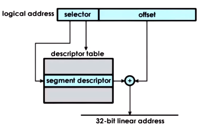
Segment-Based Memory Management - Segmentation
Virtual Address space is divided into flexible sized segments that can be mapped to a region
of physical memory and swapped between main physical memory and secondary storage, in terms of allocation the OS keeps this mapping,
in terms of arbitration the OS uses segment registers to determine if its accesing a valid memory section
The virtual address is divided into a Segment Selector and the Offset, the Selector is used to get from aDescriptor table
a Segment Descriptor which is then used to access the actual physical address of the segment
The segment is usually a contiguous portion physical memory and its size is defined by Segment Size = Segment Base + Limit Register
Allocation
The memory allocator is an essential part of the memory management subsystem of an OS that is in charge of allocating particular portions of the memory to a process
The memory allocator has mechanism that decide what are the physical pages that will be allocated to a particular virtual memory region
Memory allocators exists at the kernel level and at a user-level
- Kernel-level allocators: are responsible to allocate pages for the kernel, its state and components and track the free memory that's available in the system.
Also allocate memory for all processes static state
- User-level: used for dynamic process state (heap) for example malloc/free which request memory from the kernel free pages
Linux Kernel uses the Buddy Allocator and Slab Allocator, Buddy used for requests demanding 2^x chunks and Slab for requests of sizes with a granularity different than 2^x
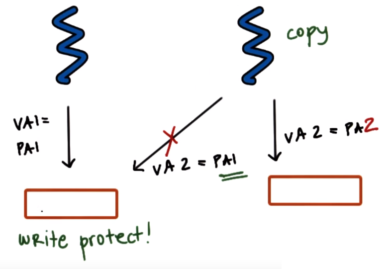
- When creating a new process we need to copy entire address space of parent process but many of information we need to copy is static (it wont change) like the code (which usually is read-only) so insteads of copying all
we map portions of the virtual address space of the child process to the same physical address as the parent, in other words certain pages of the new process are mapped to the same physical
frames of the original process so the same physical memory may be referred to by two different virtual addresses from two processes but the physical memory must be Write-protected so if
we need to make a write to this memory the OS can detect it, through the MMU which will report an access fault, and then create an actual copy only when trying to write,
this will result on copying only those page that are necesseary, this is called (Copy-On-Write (COW))
- Checkpointing refers to the action of periodically saving a process state to restart it from a checkpoint instead of from the beginning in case a failure occurs
Paging
Paging / Demand Paging refers to the process of saving and restoring pages to/from secondary storage where a swap partition resides so in general
pages are swapped between memory and the swap partion.
Periodically when the amount of occupied memory reaches a certain threshold, the OS will run some page (out) daemon
that will lookup for pages to be swapped or freed
To decide which pages will be swapped out usually the OS uses an history-based prediction algorithm like Least-Recently Used (LRU)
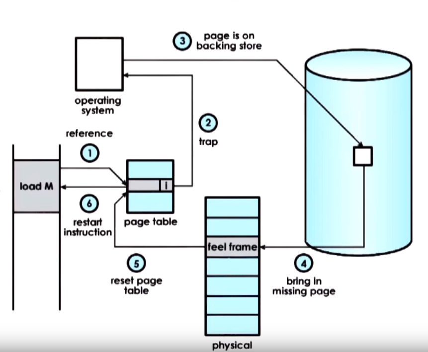
Paging General process flow:
- An attempt to reference a page is made that is not present
- The MMU raises a signal to the OS kernel (page fault)
- The OS can determine it has previously swapped the memory so it performs the correct disk access
- The page is brought into memory
- The OS updates the page table
- Control is passed back to the process that referenced the memory to the same instruction that made the reference so this time it finds a valid entry on the page table
- If we require a page to be constantly present in memory or require it to maintain same physical address during lifetime we can disable
swapping (have it pinned or pin the page), this is usually used with devices that support DMA
Inter-Process Communication (IPC)
Inter-Process Communication (IPC) are mechanisms for process interaction which help to transfer data between address spaces and
mantain protection and isolation of processes, they provide a standard and flexible way of sharing data while also considering performance
IPC refers to a set of mechanisms the OS supports to allow communication and coordination among processes
IPC requires synchronization mechanism between processes like mutexes
IPC in general could be of two types Message-Passing IPC and Shared Memory IPC.
For sharing large amounts of data Shared Memory IPC may be better and for small amounts of data using Message-Passing IPC may be more convenient
Shared memory can be access by all the process that share access to that shared memory region so accesses must be synchronize (sync for processes).
- Data structures (like mutexes and condition variables) used for sync must be stored and updated in shared memory
- Methods for process sync:
- Using mechanism supported by process threading library (like
pthreads), appropriately setting them for processes and not threads,
for example setting the right fields in the pthread_mutexattr_t and pthread_condattr_t structures when creating a mutex or condition variable (usign PTHREAD_PROCESS_SHARED)
- IPC synchronization methods supported by the OS like:
- message queues: a process writes data to shared memory and sends a ready message to the msg queue, second process receives it,
reads the data from shared memory and sends and acknowledge message back
- semaphores
Message-Passing IPC
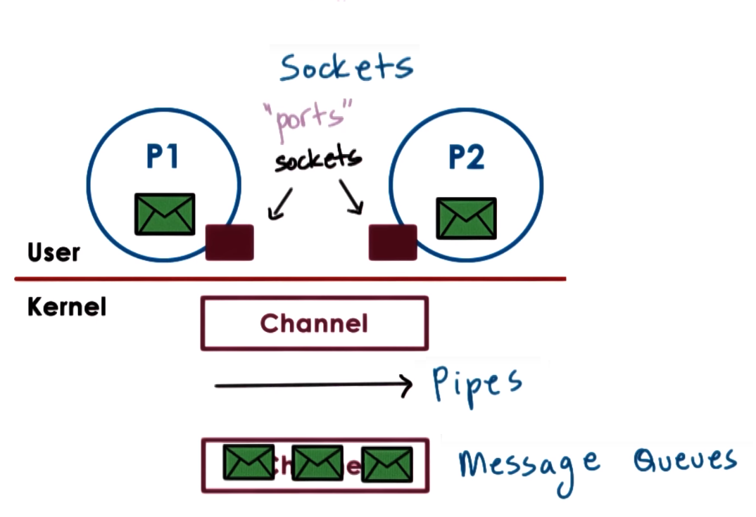
Processes exchange messages, pass messages via mailboxes, sockets, pipes, message queues, etc
OS provides communication channel like a shared buffer and processes uses standard write/send and read/recv operations to send/receive messages
OS is responsible for creating and maintaining the channel of communication (Buffer, FIFO queue, etc.)
and provides an interface (usually called a port) to communication opearations (processes write/send to a port and read/recv from a port)
Because the OS is the one that provides the interface for communication send/recv it is the one that does a system call and copying data each call of these operations
IPC is simple and easy to use because channel handles sync but can be costly due to kernel crossing and data copying (cause overhead)
Forms of Message-Passing IPC
- Pipes: Consist of stream of data between 2 endpoints, there is no notion of message instead a stream of bytes is pushed from one
process to anothe and it is usually used to connect ouput of one process to input of another. Pipes are supported on the
POSIX API
- Message queues: Carry message (data in a specific formatted form) from one process to another which can have priorities.
SysV and POSIX are APIs that suppport Message queues
- Sockets uses the
socket() call to create kernel buffer used as the channel and the uses send() and recv() operations to
pass message buffers through the channel. It associates kernel-level processing for example for TCP/IP sockets associates all
the TCP/IP protocol stack data movement (which is a kernel-level processing) will be performed when doing a send() or recv().
Sockets are mostly used for processes on different systems/machines
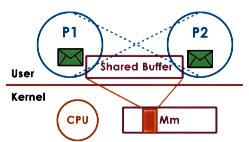
Shared Memory IPC
Processes have a portion of physical shared memory and data that both need to access will be place in this shared memory,
the shared memory could be in the form of physical memory pages or memory mapped files (multiple process read and write from the same file)
OS establishes a shared memory space and maps it into each process address space, processes directly read and write memory, OS is not involded in this communication step
OS only establishes shared channel between processes by mapping the same physical pages to the virtual address spaces of the processes
In other words VA of Process 1 and VA of Process 2 are mapped to the same physical addresses
It is efficient because OS only sets shared memory space so system calls are only needed during setup but implementation can be complex due to sync issues and establishment of a communication protocol
SysV API and POSIX Shared Memory API can be used to implement Shared Memory IPC
Linux IPC APIs
- Supports segments of shared memory, not necessarily contiguous physical pages
- Shared memory is limited by the system to a number of finite segments
SysV Operations
- Create -
shmget(shmid, size, flag): Allocates memory (segment) and needs a unique key (shmid uses hash ftok(pathname, prc_id) to create it) to identidy the shared memory
- Attach -
shmat(shmid, addr, flag): maps a virtual address of a process to a physical address using the key used with the create operation (virtual address can be specified using addr)
- Detach -
shmgdt(shmid): Invalidate an address mapping from a process to the shared memory, dettachs a process from the shared memory
- Destroy -
shmctl(shmid, cmd, buf): Actually destroying/releasing the shared memory (segment) by calling shmctl with cmd == IPC_RMID
- Although it is supposed to be the standandrd Linux shared memory API it is not so commonly used for shared memory implementations
- It uses Files for the shared memory operations that are actually temporary files that exists in the
tmpfs file system (which looks like a file system but is just data in volatile memory)
POSIX Operations
- Open -
shm_open(): Returns file descriptor to file in tmpfs used for read/write operations to shared memory
- Map-Unmap -
mmap()& unmmap(): use to map and unmap virtual address of a process to a physical address
- close -
shm_close(): Removes/uninit the file descriptor so you can longer access the file but wont actually delete the shared memory
- unlink -
shm_unlink(): Actually destroy shared memory file
Synchronization Constructs
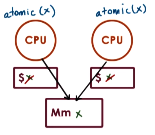
To guarantee the correctness of the synchronization construct, they need atomic instructions HW support
An Atomics Instruction is a instruction that is guaranteed to be executed uninterrupted and
provide mutual exclusion which means only one instruction at a time will be allowed to perform the operation while other concurrent atomic
instructions will have to wait. test_and_set is an example of an atomic instruction
Atomic operations bypass cache to avoid synchronization cache-coherency issues so atomics are issued directly to memory (to the memory controller)
this guarantees synchronization but causes performance due to memory access an also trigger coherence traffic (make sure to update values on cache)
Spinlock / Spinlock Mutex
- A Spinlock or Spinlock Mutex are used to protect a critical section and provide mutual exclusion among concurrent access but
in case a spinlock is locked trying to lock it from other thread does not block instead it makes the thread spin, which means repeatedly
checking to see whether the lock became free (burning CPU cycles) until the thread gets preempted maybe until its timeslice expired,
while a regular mutex would block the thread, relinquishing the CPU allowing other threads to run
Semaphore
Sempahore blocks or allows access to a resource providing exclusion like a mutex but are a general implementation of mutex, they are counting semaphores. binary semaphore == mutex
A Sempahore is basically a counter that is init to a max positive count, then a thread waits on the semaphore if the count is
non-zero it decrements count and proceeds, if its zero it blocks the thread, when finishing accesing the shared resource the
thread will post which increments the count
because they are initialized to a max count, they allow multiple thread to access the resource at the same time, the number
of threads that can access the resource are equal to the max count value
#include <semaphore.h>

sem_t sem;
sem_init(sem_t* sem, int pshared, int count);
sem_wait(sem_t* sem);
sem_post(sem_t* sem);
RWlocks
RWlocks (rwlock_t) also called shared locks or exclusive locks also restrict access to a
resource like a semaphore besides allowing to specify the type of access:
- read = never modify = shared accces
- write = always modify = exclusive accces
You can use read_lock() and read_unlock if you plan to access the resource without modifying it which allows other threads to access it as well
meanwhile you can use write_lock() and write_unlock if you want exclusive access to the resource
Higher-Level Syncrhonization Constructs
Monitors: You specify the shared reource being protected, the entry operations (like read, write, check, etc) and the
possible condition varibles that need to be signaled or modified. On entry operation it locks and perform other
checking and on exit it unloks, checks and does all the signaling
- Java has monitors, every has an internal lock and methods declared as synchornized are enrty points to the monitor
Serializers make it possible to define priorities and hide tge needs to explicitly signal and use of condition variables
Path Expressions you specify a regular expression like expression that that defines the correct sync behavior (E.g. many reads and one write)
Barriers or Rendezvous points are sync cronstructs that block until a number of threads arrive to a certain point defined by the barrier
wait-free sync (RCU) refer to no wait syncronization constrcuts that bet on the fact that it wont be conflicts due to certain concurrent operations
I/O Devices & Management
OS must provide an interface to interact with IO devices and specific components (like device drivers, interrupt handlers) that
are responsible for the I/O management with the goal of abstracting the I/O devices details from applications
Any device can be abstracted as an Interface and other Internals
- Interface = Control registers: that can be accesed by the CPU and permit the device interactions registers for command, configuration, status, data and data trasnfers
- Internals = Device Hardware: Device specific HW and logic like a MCU, memory, ADC, DAC, HW specific chips, etc
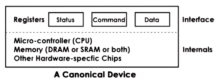
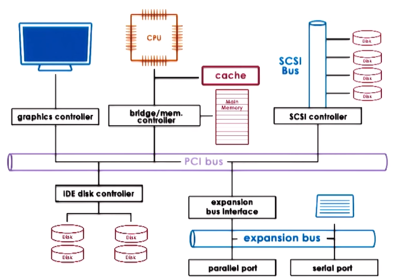
- Devices usually use a controller which is used to connect and interact with the rest of the system and the CPU complex via a
type CPU - Device Interconnect like PCI
PCI - Peripheral Ccomponent Interconnect is one of the standard and most common methods for connecting devices to the CPU
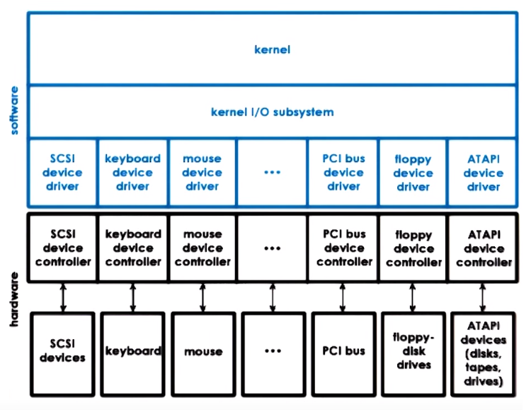
Device Drivers
Operating systems support devices via Device Drivers which are device specific software components that are responsible for
device access, device management and device control which in general refers to the logic that determines how can requests
be send and how responses and events can be notified
An OS usually includes a device driver for each different HW device that supports
Operating systems standardize their intercaes to device drivers by providing a framework so device manufacturers,
who develop the device drivers, can develop a device driver using that framework, in other words within the framework using the
specific interfaces that the OS supports
Devices Categories / Types of Devices
Block
- Operate (
read/write) on entire blocks of flixed sized of data, and this data is delivered in and out between the device and CPU.
- Individual blocks of data can be accessed directly
- Block devices examples: Disk
Character
- Operate with a serial sequence of characters, they
get/put data in a character granularity
- Character devices examples: Keybord
Network
- Operate with a stream of data chunks of potentially different sizes
- Special case of devices that could deliver more than a character adn their granularity is not necessarily a fixed block size
- Character devices examples: Network card
Device Access
CPU to Device & Device to CPU
OS usually uses a special file abstraction to represent each of the devices available on the system, so standard operations and mechanisms to interact with files
can also work with devices, for example read, write or other operations on the file representing the device will be handled in some device-specific manner.
On UNIX-like systems these representations can be found underneath the /dev directory and are treated by special file system (devfs & tmpfs), not stored on a real file system
Pseudo/Virtual devices do not represent actual HW but provide special functionality that can be used by the system
CPU to device (CPU -> Device) access can be done through Memory Mapped I/O or I/O Port Model while path from
a device to CPU (Device -> CPU) can take two routes: devices can generate Interrupts to signal an event to the CPU or
the trhough Polling the CPU polls the device by reading some of its registers
Memory Mapped I/O part of the physical memory dedicated for device intercations, this portion of memory is controlled by
a specific type of registers, the Base Address Registers (BARs) these defines how much memory and startst at which address
will be used by a particualr device, these registers are configured during boot by the BIOS
PCI interconnect devices to the CPU through memory mapped devices, access to devices registers appear to the CPU as memory
locations at a specific physical address that the CPU can access (load/store <-> read/write) so when the CPU reads or writes
to these locations the interconnect realizes the access should be routed to the apporpiate device
I/O Port Model - CPU can also access devices via special in/out instructions, specifying the target device (via I/O port)
Typical Device Access - PIO & DMA
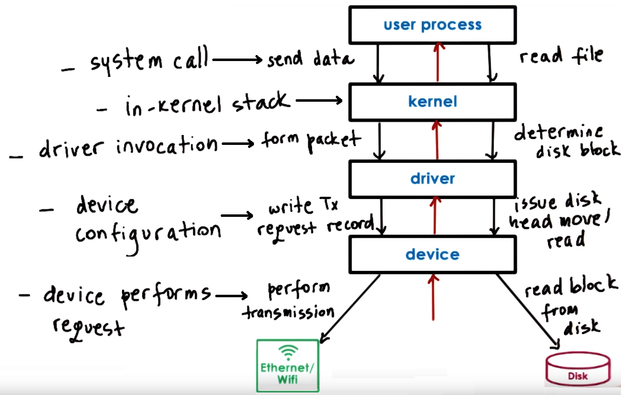
- Typical Device Access Flow
- Process need to perform an operation that requires HW access so it performs system call to kernel. E.g. Send data via network
- Kernel runs the in-kernel stack of related to the particular device. E.g. Run TCP/IP stack to from packet
- The in-kernel stack will call the device driver to performm the particular device config. E.g. write the Tx request registers and data to device
- Device driver performs request to the device. E.g. Perform transmission data
We can also access the device directly from the user-level bypassing the OS, in this case we need a user-level driver/library
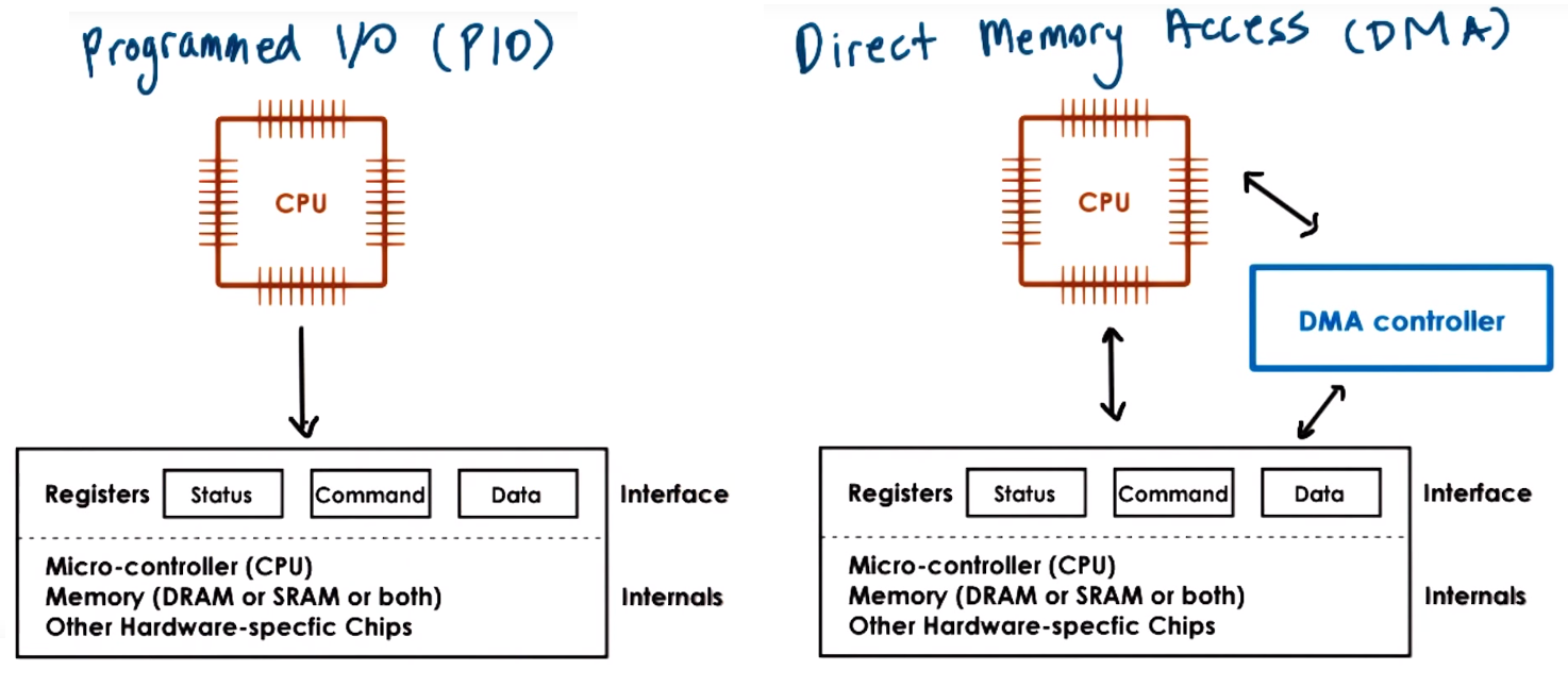
- Program IO (PIO) refers to atype of interaction between the CPU and a device in which the CPU programs the devicee registers then reads or writes them to perform a request
meanwhile Direct Memory Access (DMA) is another type of interaction that relies on a DMA controller (which refers to HW that must be supported by the device) in which
the CPU programs the device registers and configures the DMA controller in the device so the data movement is controlled by the DMA directly, from memory to device or from device to certain memory location
(for this we also need to make sure data is in physical memory until trasfer completes and it is not swapped out to secondary storage)
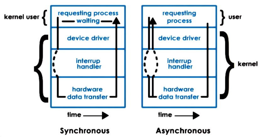
Synchronous & Asynchronous IO Operations
- Synchronous: The user process calling the operations will block waiting for IO and eventually become runnable when the response becomes available
- Asynchronous: The user process is allowed to continue after issues IO call, at a later time it can check if results are ready or
the process is notified by the device or OS that the operation has completed
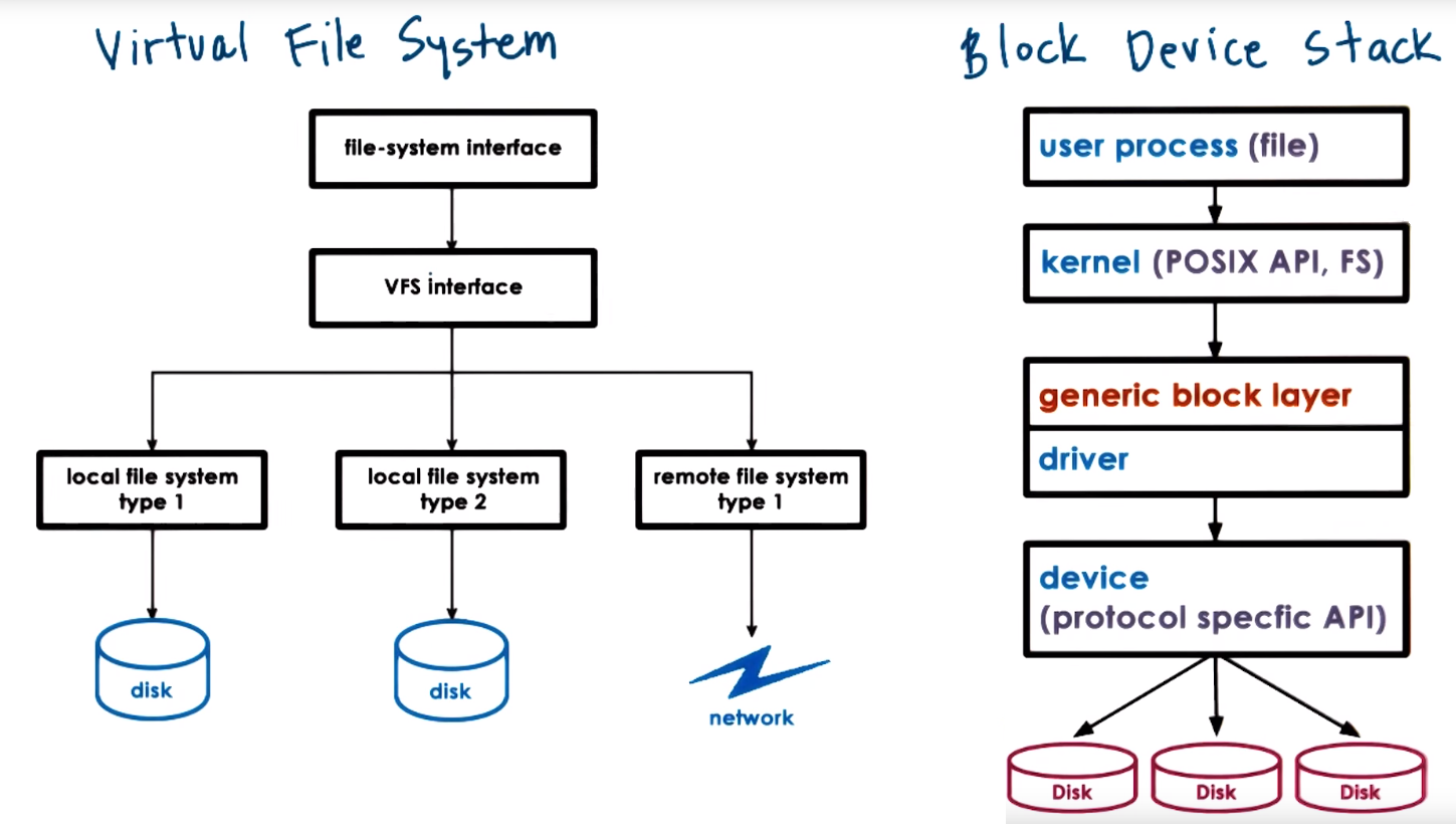
Block Device Stack, VFS, inodes
A file is a logical storage unit mapped to a physical location
Block devices are typically used for storage and for storage related interaction processes uses files, while the
FileSystem that is part of the kernel knows how to interpret the read/writes coming from the application and
determine where is the file, what particular portion needs to be accessed, etc. then passes the request to a generic block layer
which standardized all types of block devices and eventually calls the specific device driver
Virtual File System (VFS): Hide from applications all details regarding the underlying file system, its data structures are maintained by the OS Filesystem component
- OS represents files via file descriptors (created when a file is first opened) and used to perform operations (read, write, sendfile, lock, close...)
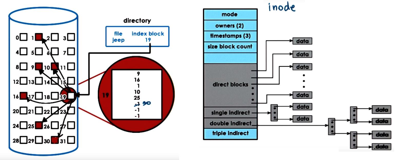
- For each file the VFS maintains an
inode which is data structure that holds a list of all the data blocks of a file besides (inodes must be on persistant storage)
the file persmissions, size, device it belongs, etc
- A directory is just a file which contents include information about files and their
inodes
- A file is identified by its
inode which are uniquely numbered, a filenam eis mapped to an inode
To reduce disk accesses disk rely on buffer cache in main memory and and prefetching to this cache, so the file is read/write from the cache and periodically flushed to disk (fsync()), also
the OS could try to reduce disk accesses by doing IO scheduling or in other words ordering how disks accesses will be scheduled, maximizing sequential access
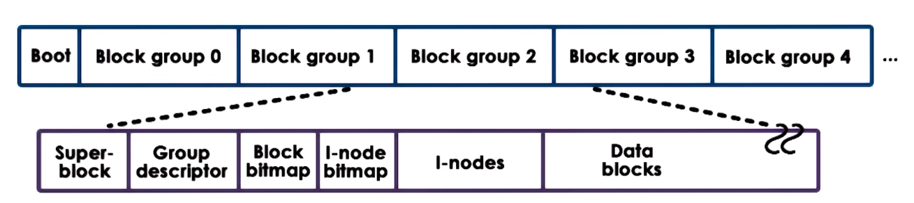
ext2 Extended Filesystem version 2
Organization of a partition used as an ext2 linux file system
- Block 0 = Boot: contains code to boot the system
- Block Group: Rest of the partition divided into groups. Each divide into:
- Super-Block: Cotains information about the overall block group (number of
inodes)
- Group Descriptor: Conatians overall state of the Block Group
- bitmaps Used to find a free block
inodes data structures to hold a list of all the data blocks of a file, in this section there can be from 1 to a max number of inodes (in ext2 each inode is 128 bytes), one per file,- Data Blocks Blocks that hold actual data
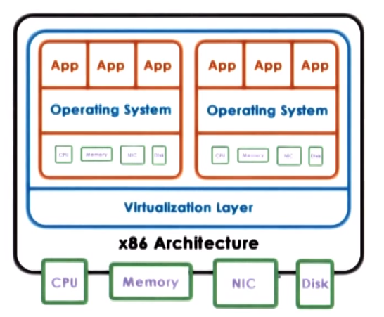
Virtualization
Virtualization Allows concurrent execution of multiple OSs (and their applications) on the same physical machine, in order
to run very diverse workloads or application on the same physical HW.
With Virtualization each OS thins that it own the HW resources but in reality it owns only virtual resources, the term
Virtual machine (VM) is used to refer to the combination of OS, applications and virtual resources (the guest) running on a
platform with actual physical resources (the host)
To support virtualization a platform needs a virtualization layer that provides the functionality needed to manage the physical HW
and guarantees isolation between the VMs running, this is also called Virtual Machine Monitor (VMM) or Hypervisor
Consolidation refers to the ability to run multiple virtual machines on a single platform
Migration refers to the ability to easily clone a VM to another platform, providing greater availability
Virtualization models
a VMM or Hypervisor is responsible for the management of the physical resources and supports execution of the VMs,
usually integrading a privileged VM that runs a standard OS that has full HW privileges, runs all device drivers controlling how the devices are used besides
performing other configuration and magement tasks.
Xen and VMware use this model
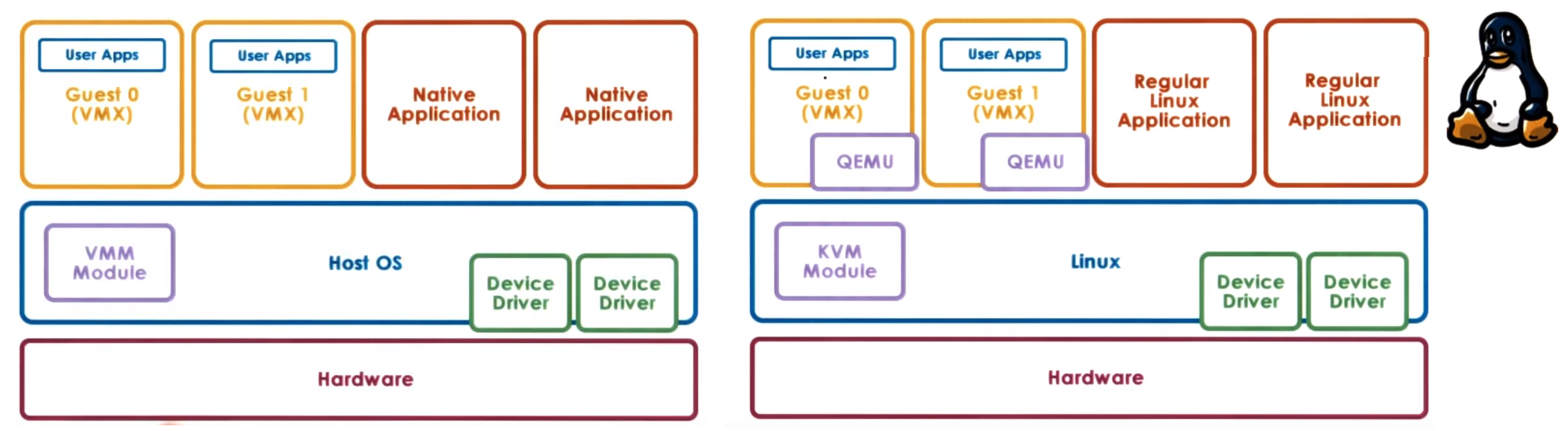
Type2 - Hosted
Uses a complete Host OS that manages all the HW and integrates a Virtual Machine Monitor module (Hypervisor Module)
which provides hardware interfaces to the VMs, the VMM module will invoke drivers and otehr componets of the Host OS to access the HW.
This module allows to run VMs along with native application directly on the Host OS
KVM (Kernel-Base VM) based on Linux use this model, needs the KVM kernel module and QEMU for HW virtualization
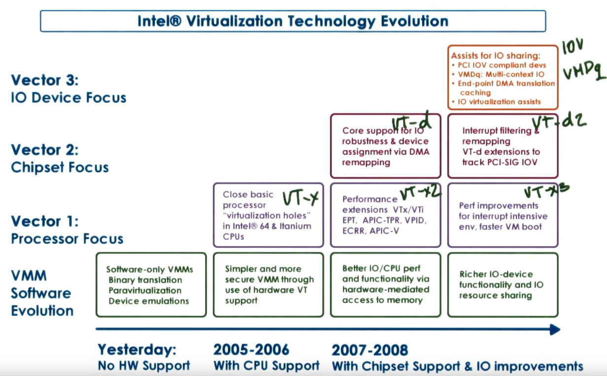
Virtualization HW considerations:
- Intel Vanderpool Technology (Intel-VT): Refers to HW to support for virtualization which includes support for:
- extended page tables that include VM identifier the MMU can use to know if a certain page belongs to a VM guest
- IO virtualization where devices can have multiple logic interfaces and each interface can be used by a separate VM
- Interrupt routing logic to determine that an interrupt belong to a certain VM and route efficiently to it
- Special virtualization instructions
- Modern HW usually has more than 2 protection levels and include protection modes.
x86 has 4 protection levels and 2 protection modes root (host) mode & non-root (guest) mode (within each of these modes the 4 protection levels exists)
- ring 0: highest privilege can access all of the resources and execute all instructions if in root mode certain intructions are not permitted in non-root (OS runs in this level)
ring 1 & ring 2
- ring 3: lowest privilege, restrcited access to some instructions (apps run in this level)
CPU Virtualization
guest non-privileged instructions are executed directly by the hardware the hypervisor does not interfer with every single instruction
issues by the guest OS, as long as the guest OS operates within the resources that were allocated by the hypervisor everything is safe
privileged instructions are trapped to switch control the hypervisor (that runs in a privileged level) which determines whether the operations is allowed,
if is legal it emulates the behavior the guest OS was expecting from the HW in case it is illegal it can terminate the VM send an error or take other action
Binary Translation (Full virtualzation) refers to the idea of dynamically translating a VM binary in order to never issue certain priviledge instructions,
this is done via dynamic binary translation and qith the intention of dont actually modify the VM guest OS code which means that a sequence of instructions
that are about to be executed are dynamically translated if needed. VMWare uses this approach
Paravirtualization refers to the idea of modifying the VM guest OS code so it knows it's running in a virtualized enviroment,
in general modify system calls to call the hypervisor (hypercalls). Xen and Citrix use this approach
Memory Virtualization
For full virtualization it is expected that all guests see contiguous physical memory starting at address 0, for this
guest has a page table that map virtual to physical address and the hypervisor has table that maps physical to machine addresses
- virtual address: addresses uses by the applications in the guest OS
- physical address: addreses the guest thinks are the addreses of the physical resources
- machine addresss: actual physical addresses on the syste
For Paravirtualization since the guest is aware of virtualization it explictly registers page tables with hypervisor
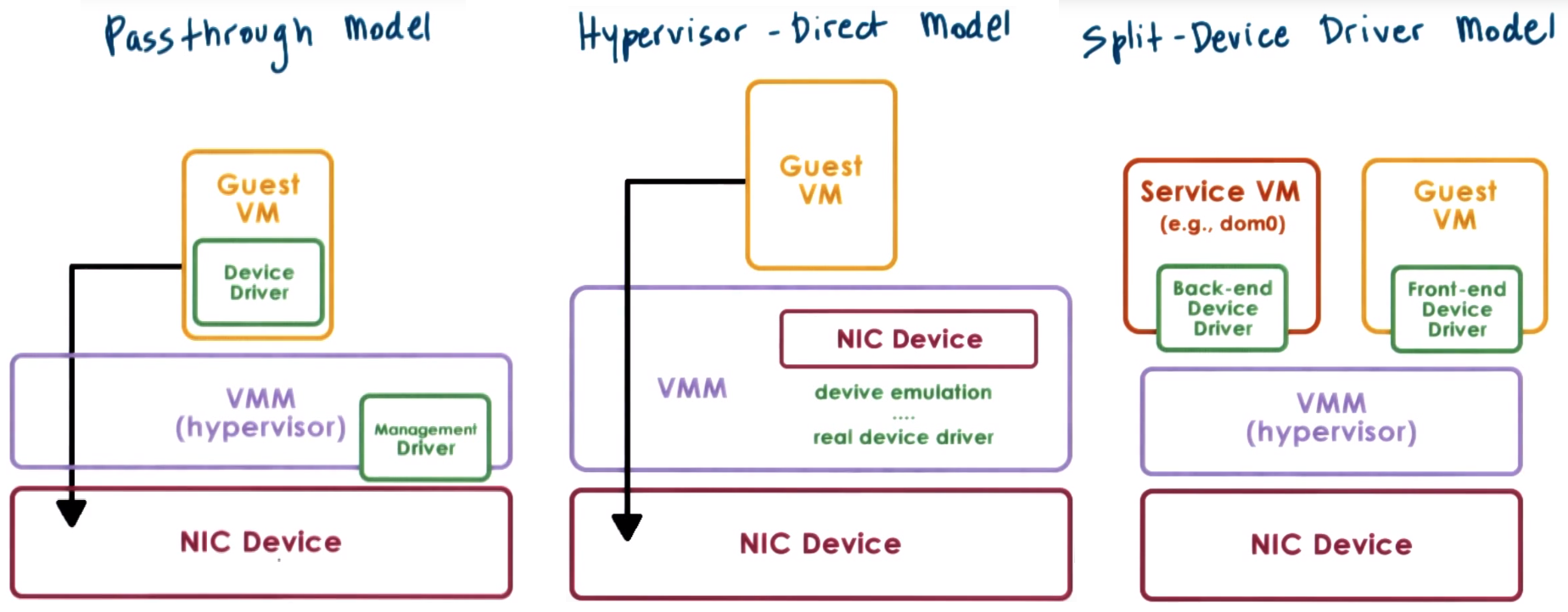
Device Virtualization
- Models for devices access in virtualized enviroment:
- Passthrough Model or VMM-Bypass the hypervisor configures device access permissions, this means hypervisor allows or prevents a certain
guest OS to have access to the memory region where the control registers for that device exist
- Direct Model Hypervisor intercepts every device access performed by the guest VM and emulates device operation,
by translating the operation and using real device driver managed by the hypervisor
- Split Device Driver Model: All device access are controlled in a way that involves a front-end driver in the guest VM (device API) and a back-end driver in the hypervisor,
applies to paravirtualized guests
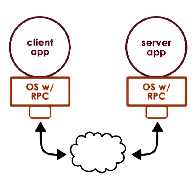
Remote Procedure Call (RPC)
RPC is an special IPC mechanism that specifies process interaction via a procedure call interface (standarized interface)
General IPC mechanisms focus on providing the basic capability for moving data among address space without defining any protocol or standarized interface
RPC is intendedn to simplify the development of cross-address space and cross-machine interactions
RPC offers high-level interface that capture all aspects of data movement and communication of a client-server type of interactions,
this includes: communication establishment, requests, responses, acks, etc. Abstracting all of this from the application that uses RPCs
and hiding complexities of cross machine interactions
Fuction under a sync call semantics in which a call to a procedure call blocks the thread waiting for a response
RPC can handle type checking and cross-machine conversions (like Endianness) and support the usage of different transport protocols
RPCs are like function calls that are performed/executed remotely
RPC steps:
- register sever registers procedures, which mean advertising what are the procedures it supports (annonces procedures and arguments required for operations)
- bind: Client finds and binds to a desired server
- call: Client makes an RPC call and control is passed to client stub and client code blocks
- marshal: client stub serialize arguments into a buffer, this is called marshalling
- send: client sends the message, this involves whatever transmission protocol is used
- receive: Server receives message and all the necessary checks are performed
- unmarshal: server extracts, parse arguments and creates local data structures, this is called unmarshalling
- actual call: server calls the implementation of this procedure
- result: Server performs operation and computes result
RPCs rely on an Interface Definition Language (IDL) which serve as a protocol to define what are the procedures supported
by a server and what arguments it needs for the various operations, in summary an IDL is used to describe the interfaces the server exports (supports).
IDL needs to specify: procedure name, procedure version number, arguments and result types, these are usually in a standard non-programming languge
(like XDR .x files) and then are converted to a specific programming language
An OS that support RPCs needs to have a access to a registry of all the available services, this can be distributed, machine specific
Pointer arguments in a remote procedure call are a special case that result in RPCs not supporting pointer arguments or serializing all data the pointer points to send as part of procedure call
RPCs have a special error notification that intents to catch all possible ways in which the RPC can fail
Distributed File Systems (DFS)
Systems hide the fact that there may be different types of storage devices by using a virtual file system interface, with this
it can also hide the fact storage is maintained on a remote file system that is being accessed over the network
Enviroments in where there are multiple machines that are involved in the delivery of the file system service, together form a Distributed File System (DFS)
In genereal any filesystem that can be organized as follows is a DFS
- client that access the files and server with the actual files are on different machines
- file server is distributed on multiple machines (files are replicated and/or partitioned)
- files are stored and server from all machines (peers)
In general a DFS allow clients to store part of the files (cache files) it wants to access locally (blocks) and frequently interact with the server
to report changes
Network File System (NFS)
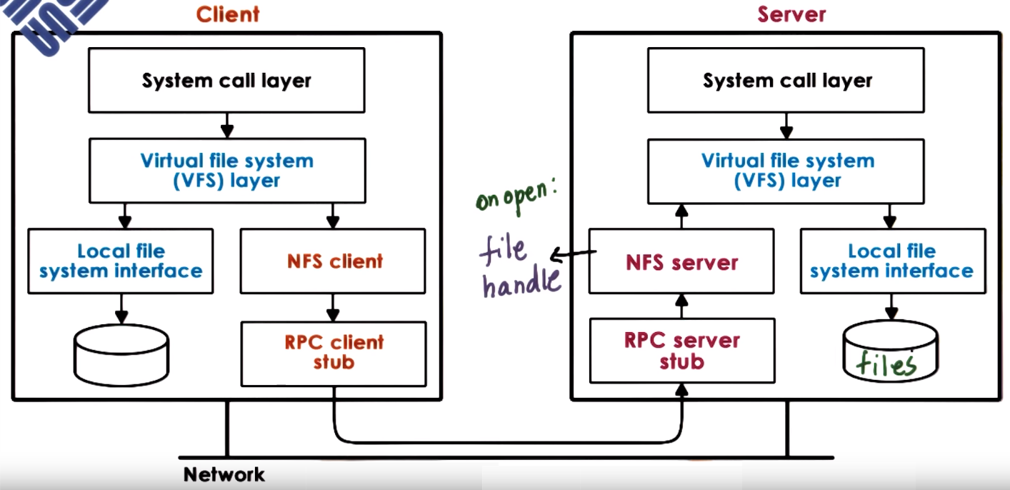
Clients access server over a network via a VFS layer using the same types of file descriptor used to access local files, VFS determines
whether the file belongs to the local FS or it needs pass control to the NFS client that interacts via RPCs with the NFS server which
issues an operation to the virtual file system to acces the actual file in the server
When opening a file a handle is generated in the server that identifies the server machine and local file in the server,
this handle is send to the client, the NFS client maintains and uses this handle when performing operations
NFSv3 (stateless) and NFSv4 (stateful) are the current NFS versions that uses a session-based (update on open file and flush/update on file close)
approach when non-concurrent access are needed in general but also include periodic updates (default: 3s for files and 30s for directories) and for
concurrent access support locking to files using a lease-based approach that defines validity of the lock
Distributed Shared Memory (DSM)
Distributed Shared Memory (DSM) is a service that manages the memory across multiple nodes so that applications running on top will have
an illusion that they are running on shared memory machines,
Each node/system owns some portion of memory so holds some state and allows access (reads/writes) from any node and must comply with a consistency protocol
to make sure the shared accesses to the state makes sense, acceses in general must be ordered and observed by all the nodes as if all where accesing the same physical memory
DSM perform distributed state management operations, the state stored in memory is shared among different processes that are running on different machines.
DSM is responsible for managing locally stored state and providing access to to this local stored state but also at the same time accessing the state that is stored by other nodes/machines
DSM permits scaling beyound single machine memory limits
DSM can be implemented fully in HW relying on commodity interconnect technologies like Remote DMA (RDMA)
which can connect machines and provide low latency accessing remote memories, in this implementation the OS is under the impression
that it has much larger physical memory so the OS can establish virtual to physical memory mappings that correspond to memory locations in other nodes
DSM can be implemented in SW (at the OS level or application level), in this case the software would have to detec memory accesses that are local and which are remote to
create and send messages the appropiate node when necessary and be involved in in the memory sharing and consistency support
DMS besides read/writes introduce sync which make sure all the updates that have happened prior to a sync will become visible,
this operation must be performed by the process who wants to signals and the process who wants to guarantee they have the latest updates
Other Notes
- A registry, is used to store and retrieve configuration information.
- Fairness in scheduling means all task should be able to run for amount of time proportional to their priority
- In a Red-Black Tree as nodes are added or removed from the tree,
it will balance itself so all the paths from root to leaves are approx. of the same size
General Unix
Everything is a file
A file is a good abstraction of either a sink for, or source of, data. so it is an excellent abstraction of all the devices one might attach to the computer
The standard library of a UNIX platform is generically referred to as libc
- Provides fundamental calls such as
open(), read(), write() and printf()
File descriptors
- the file-descriptor is the gateway into the kernel's abstractions of underlying hardware
- It is the handle user-space uses to talk to the underlying device.
- The value returned by an open call is called a file descriptor and is essentially an index into an array of open files kept by the kernel.
- File descriptors are an index into a file descriptor table stored by the kernel. The kernel creates a file descriptor in response to an open call and associates the file descriptor with some abstraction of an underlying file-like object
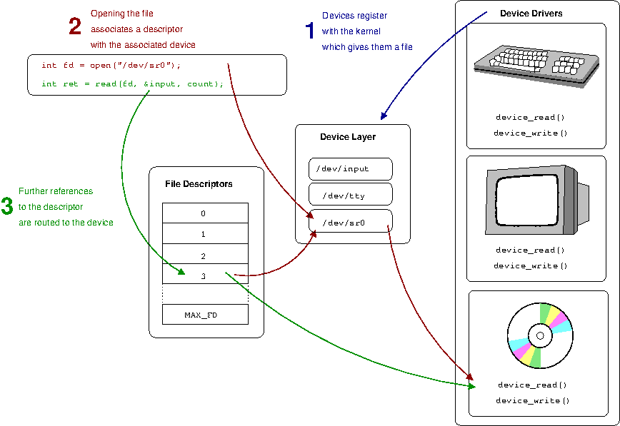
- To be able to communicate with a hardware device, the operating system requires a programmer to create a device-driver. The device-driver implements the API or functions that will be called by the kernel
- When a file is opened the kernel is using the path information passed as parameter to map the file-descriptor with something that provides an appropriate file operations (read, write, etc API)
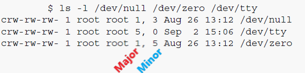
- Physical devices on the host are represented by a file in a special file system such as
/dev. In UNIX-like systems, so-called device-nodes have what are termed a major and a minor number, these numbers allow the kernel to associate particular nodes with their underlying driver
The Shell
- The shell is the gateway to interacting with the operating system.
- Its fundamental task is to allow you to execute programs
- They also allow us to redirect files, to execute multiple programs simultaneously, script complete programs, etc.
pipe
- The pipe is an in-memory buffer that connects two processes together
- Writes to the pipe are stored by the kernel until a corresponding read from the other side drains the buffer.
C standard (C99)
- The C standard takes care not to define areas that are architecture dependent
- The "glue" between the C standard and the underlying architecture is the Application Binary Interface (ABI)
- The C99 standard only mentions the smallest possible size of each of the types defined for C.
- The best size for types can be different across different processor architectures and operating systems
Application Binary Interface (ABI)
- Each architecture and operating system conforms to an specific ABI which is written for a specific processor and operating system combination
- Fills in the details between the C standard and the requirements of the underlying HW and OS system
GNU C (gcc)
- The GNU C Compiler, more commonly referred to as
gcc, almost completely implements the C99 standard
- it also implements a range of extensions to the standard which programmers will often use to gain extra functionality, at the expense of portability to another compiler
gcc can be directed to adhere strictly to the standard using the -std=c99 flag which will warn or create an error when things that are not in the standard are done
Computer Architecture
The general principle behind all computer operations is The CPU executes instructions read from memory which can load/store from memory
or operate on values stored in registers (like add, substract, bitwise operations, etc).
Executing a single instruction usually consists of a particular cycle of events: fetch, decode, execute and store/write back
- Fetch: Get the instruction from memory into the processor
- Decode: Internally decode what it has to do
- Execute: Actuallly perfomed the decoded operation
- Store/Write back: store the result back to a register or memory
The CPU keeps a record of the next instruction to be executed in the instruction pointer which usually increment sequentially but can be changed by branching instructions
latency refers to to time the CPU takes to access data in main memory
Instructions in a RISC processor are much more simple
logic of ordering instructions can be moved from the processor to the compiler. This means that compiler writers need to be smarter to try and find the best ordering of code for the processor.
Computer code generally exhibits two forms of locality
- Spatial locality suggests that data within blocks is likely to be accessed together
- Temporal locality suggests that data that was used recently will likely be used again shortly.
The cache is a very fast copy of the slower main system memory, small chunks of mirrored main memory.
- line size: one chunk of mirrored main memory, usually 32 to 64 bytes
The communication channel between the processor and the peripherals is called a bus.
An interrupt allows the device to literally interrupt the processor to flag some information
The general principle is that the operating system has configured an interrupt descriptor table which pairs each of the possible interrupts with a code address to jump to when the interrupt is received
Most drivers will split up handling of interrupts into bottom and top halves
It is generally the job of the operating system to ensure that upon entry to the interrupt handler, it saves any state and restore it when returning from the interrupt handler
The most common form of IO is so called memory mapped IO where registers of a device are mapped into memory
References
- Computer Science from the Bottom Up (2016), Ian Wienand. Stanford California, USA
- Operating System Concepts, 10th Edition (2018), Abraham Silberschatz; Peter Baer Galvin; Greg Gagne. Hoboken NJ, USA : Wiley
- CS8803: Introduction to Operating Systems by GeorgiaTech Udacity Online Course
