In a Digital System the information is in discrete and finite values
Combinatorial Logic - Logic that does not rely on the previous state of the system to set the current output state. The outputs are purely dependent on the inputs
Sequential Logic - Logic that typically uses flip flops and the current output state influences future output states.
Truth Table - A table showing a logic circuit's possible inputs and the outputs that will result.
reset types:
asynchronous
General reset signal of a digital system, it's effect does NOT depend of the clock
Every design must have a unique async reset that . Usually active in low
synchronous:
Depends of the clock signal used by the digital system, used for reset of internal modules of the design
sync reset takes effect in the edge of the clock
The clock of a system must NOT be controlled inside of the module by any type of logic, it can be controlled outside of the module with clock gating techniques
A digital system must be LTI (Linear Time invariant) system, this means it's characteristics of input-output does not change over time
In a synchronous design everything is related to the clock signal and it must behave in predictable and reliable way by not violating setup and hold times. It needs to avoid delay chains and combinational chains
Types of HDL description:
Structural: Define components and it's interconnections (the connections between the components)
Behavioral: Describing how a digital circuit behaves or responds to certain stimuli. Letting the compiler infer the HW
RTL (Register Transfer Level): Defined the way the data flows through the design
FPGA
FPGA - Field Programmable Gate Array. Programmable logic blocks interconnected through a programmable switch fabric or mesh
LUT (Look-Up Tables) are a key component on the creation of some FPGAs since they can be used to create combinational logic, they are implemented using some memory (ROM, RAM, etc.) and a series of multiplexers cascaded
Most manufacturers combine LUTs with other components (like registers, adders, multipliers, etc.) to create the basic logic modules used to implement an FPGA
E.g. Stratix Families use ALM (Adaptive Logic Module) that combine some combinational logic, adders and registers.
HDL code is then synthetized into these adaptive logic modules. These logic modules are then organized into LABs (Logic Array Blocks) (each LAB contains 10 ALMs for example)
LABs are interconnected to implement a design
FPGAs components/organization:
Programmable core logic
Programmable I/O, I/O elements (Can support current control, slew rate control, pull-up/down resistors, open-drain or tris-state output control, etc.)
High-speed transceivers: Some FPGAs can include high-speed interfaces for protocols like Ethernet, PCIe, etc.
Programmable memories: Memory block that can be configured as Single/dual RAM. ROM, FIFO buffers, etc.
Programmable DSP blocks: Usually embedded multipliers and adders to implement high-performance MAC operations
Clock Network and Programmable PLLs logic: For clock interconnection and clock generation
Configuration device: external device to the FPGA which is usually a flash memory that contains the settings for the programmable components of the FPGA
SoC FPGAs can contain an FPGA, a processor (E.g ARM core) and other peripherals in the same chip
The main inputs of the designer are the design files (usually HDL code) and the tools settings & constraints (timing constrains, IO timing requirement, pin placements, etc.)
TCL (Tool Command Language) scripting language used to configure design tools
FPGA development process:
Synthesize – convert Verilog into a simplified logic circuit (low-level constructs or primitives).
Map – Identify parts of the synthesized design and map them to the blocks inside the FPGA. Map the logic (low-level constructs) produced by the Synthesize step to specific device blocks of the FPGA
Place and Route (Fitting) – Allocate specific blocks inside the FPGA for the design and Make the connections between blocks required to form the circuits. This means to plan which blocks go where and exactly how to interconnect them
Configure – Send the bitstream to either the FPGA or a configuration device
Timing Analysis – Performs timing analysis to inform how well the design meets the specified timing constraints
FPGA Design
some FPGAs have blocks that are essentially look up tables. Some FPGAs use cells based on multiplexers instead of look up tables, and most combine some combinatorial logic with a configurable flip flop of some kind.
constraint
Physical constraints refer to pin placement and IO standard requirements and Timing constraints refer to delays and setup/hold timing requirements
A PCF file has a simple format and can set constraints on pins that we can use to maps Verilog symbols pins on the FPGA
A constraint tells the system something it must do during I/O mappings.
For example it can tell the system that the timing between two points has to be no more than 20 nS
Another example you can provide a clock constraint that will tell the tool the clock frequency you intend to use and it will tell you if you have delays that would cause problems (not meeting timing)
Power an Thermal main considerations in an FPGA design
Design of the Power Distribution Network (PDN) which is the one that delivers power to the FPGA
Thermal power dissipation of the design which determines operational temperature of the FPGA
The time scale setup is done with the timescale directive so for example
timescale 1s/1m express delays in seconds and the tells the simulator should keep track of time down to 1 millisecond.
In other words it says we will express delays in seconds and the minimum precision the simulator must keep is down to ms so delays
like: #0.1, #0.5 would be valid (it would be 100ms and 500ms)
Timing constraints
Setup Slack = (Time it takes clock to arrive) - (Time it takes data to arrive)
+ Setup slack is positive it means data arrives first than clock so the timing requirements are met
- Setup slack is negative it means data arrives after the clock so there is a timing violation
Hold Slack = (Time it takes data to arrive) - (Time it takes clock to arrive)
Timing Constraints categories:
Other & Exceptions Where timing for that particular path or IO timing doesn't matter like LEDs, Switches, static lines, etc. because it has multiple cycles to settle
Clocking - define master clocks and generated clocks
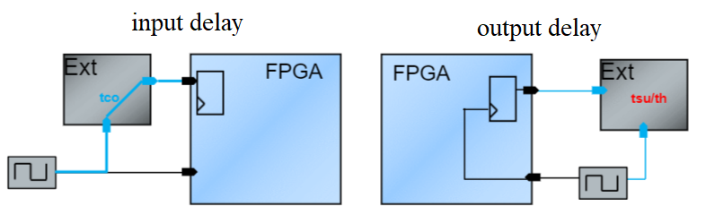
IO Timing - define setup, hold and clock to output timing requirements for each IO port. These constraints specify timing requirements of an external device
input - specify delay to a port from an external device, relative to a clock
output - specify delays from port to external device relative to a clock
Hold violations usually show up when chip timing paths are fastest and setup violations usually show up when chip timing path are slowest
bitstream
bitstream (binary configuration file), you write Verilog and the tools create a bitstream that you download into the FPGA
Some FPGAs are actually very similar to memory devices. Some are nonvolatile and some require something (like a configuration memory chip or a CPU) to load them every time, but essentially you write to them the bits (bitstream) that configure the connections and options that wire up the circuit you've designed in a HDL
The processes of taking your Verilog and creating a file that can be sent to the FPGA or a configuration memory is a workflow so an FPGA toolchain converts Verilog code into a configuration bitstream
the bitstream isn't an executable. It just defines how the internal blocks of the FPGA connect together and possibly sets options for some of the blocks.
Verilog and SystemVerilog
During simulation, Verilog & SystemVerilog act like programming languages, allowing to write constructs that would not be transferable to the FPGA
Blocking assignment (=)
The assignment occurs before any subsequent assignments (that is, it does not occur in parallel).
It is a one step process: 1) Evaluate the RHS and update the LHS of the blocking assignment without interruption from any other Verilog statement.
Non-blocking Assignment (<=)
The assignment occurs in parallel with other assignments in the same block. That is, all the assignments in the block happen all at one time (in simulation this is at the end statement)
It is a two steps process: 1) Evaluate the RHS of no-blocking statements at the beginning of the time step. 2) Update the LHS of non-blocking statements at the end of the time step.
RHS = right-hand side equation and LHS = left-hand side expression
The always statement tells Verilog that the code following should execute whenever any of the inputs you use in it change
The Verilog HW description code becomes connecting wires that wire up circuit elements just as though you had a sea of gates on a PCB and you connected them with wire wrap
Statements can either be synthesizable which means it can produce HW or non-synthesizable which cannot produce HW but can be used to describe elements and logic in a test-bench
The context determines whether a statement is synthesizable
A module represents an abstraction of an specific task. The highest level module (Top Level) should only have the instantiation of the other modules that make up the design
Continuous assignments are done using the assign keyword
It is used to define a concurrent assignation
It is used to assign values to ports (inputs/outputs) and nets
SystemVerilog is a superset of Verilog
Altera recommendation is to use logic and bit instead of reg and wire with procedural blocks for HW synthesis
When there a multiple assignments using wire is recommended
A PB (procedural block) is behavioral description but when interpreting it can be read as a sequential block. We cannot use nets in a PB
All selection (if, case) must include all possible combination to avoid generating latches and errors
always: use logic and blocking assignment (=) for combinational logic and non-blocking Assignment (<=) for sequential logic, must specific sensitive list of signals E.g always @(sel, dat_1, dat_0) begin ... end
always_comb: used to describe combinational logic, use logic and blocking assignment (=), no need to add sensitive list
alwyas_ff: used to describe a FF, use logic and non-blocking Assignment (<=) required to put clk and reset in the list of signals
always_latch: Used to describe latches
Data and Numeric Representation
Allows numeric representation of 4-states than can occur in HW:
The X values is used to represent unknown or don't care
The Z value is used to represent unconnected or tri-state design logic
0 logic zero
1 logic one
A number is represented by the format: <number of bits> '<base identifier> <digits>. The underscore (_) can be used as separator
Examples
4'd5 => 0101
8'b1_0101 => 00010101
8'hF => 00001111
-8’b101 => 11111011 (complement 2 of 101)
12'hXA => xxxxxxxx1010 (Hex fill with X)
-4'shA => 0110 (4 bits Hex with sign)
Types and Data Types
SystemVerilog standard defines that signals in a design have both a type and a data type
type indicates if the signal is a net (wire, uwire, wand, wor, tri, triand, trior, tri0, tri1, trireg, supply0 and supply1) or variable (var).
data type defines if data is 2-state (bit, byte, shortint, int, longint) or 4-state (logic, integer, reg, time)
Data types Summary
(var) data type
Description
integer
4-states, 32-bits signed integer
real
64-bits floating point
time
4-states, 64-bits signed integer
realtime
64-bits floating point used for storing time
reg
4-states, user defined size
logic
4-states, user defined size
shortint
2-states, 16-bits, signed integer
int
2-states, 32-bits, signed integer
longint
2-states, 64-bits, signed integer
bit
2-states, 1-bit
byte
2-states, 8-bits, signed integer
shortreal
32-bits floating point
void
indicates no-storage (or returns nothing)
A wire has to be constantly driven to some value because is a net. A reg is more like a regular variable, you can set a value in a reg and it sticks.
Variables cannot be driven by multiple sources so it is NOT possible to have multiple continuous assignments write to the same variable
or to combine procedural assignments with continuous assignments. In general a signal declared as a variable only has a single source
Only nets can have multiple sources, such as multiple continuous assignments and/or connections to multiple output ports of module
integer and time are variables that are 4-state data types with predefined vector sizes. int, byte, shortint and longint are variables that are 2-state data types with predefined vector sizes
SystemVerilog uses the more intuitive logic keyword to represent a general purpose, hardware-centric data type
There is no correlation whatsoever between using a reg variable and the hardware that will be inferred. It is the context that determines the hardware that will be represented (combinational logic or sequential logic). A reg may, but doesn't always, infer a flip flop
Semantically, a variable of the logic data type is identical to the Verilog reg type except that the reg keyword cannot be paired with net type keywords
The real (64-bits) and shortreal (32-bits) types are used to store floating point numbers, they are not synthesizable
logic, bit, byte, ... are data types they indicate the number of signal states the variable can have. However,
when any of these is used by itself, a var (variable) is implied.
// Equivalent declarations but with state representation difference
// Uses 4-state
var logic [63:0] addr;
logic [63:0] addr;
var [63:0] addr;

// Uses 2-state
var bit [63:0] addr;
bit [63:0] addr;
A Verilog net type (wire, wor, wand) defaults to being a 4-state logic data type but you can be explicit and use a 4-state data type. There are no 2-state net types
// Equivalent declarations for a 64-bit wide net
wire logic [63:0] data;
wire [63:0] data;
Usage for the C-like 2-state types, like int and byte
For modeling more abstract bus-functional models, where is not necessary for the model to represent detailed hardware or logic states like X or Z
For interfacing Verilog models to C or C++ models using SystemVerilog's Direct Programming Interface (DPI).
Can be as the loop-control variable in for loops since the loop control variable is typically just a temporary variable that disappears in the synthesized gate-level representation of a design
One problem you wind up with in Verilog is that if you make up a name, the compiler (by default) will assume you mean for it to
be a wire unless you tell it otherwise. if you misspell a name, it just becomes a new wire and then you can’t figure out
why your code doesn’t do what you want. that's why we use 'default_nettype none
The 4-state variables, such as reg, logic, and integer, default to beginning simulation with all bits at a logic X.
In this state are considered uninitialized, until a first value is assigned to the variable for example, by the design reset logic
These variables can be defined to begin simulation with some other value using in-line initialization, but this is not synthesizable
All 2-state date types begin simulation with a logic 0. It is legal to assign 4-state values to 2-state variables.
bits that have an X or Z value in the 4-state type will be translated to a logic 0
It is preferable to use 4-state types to represent synthesizable RTL models. The 4-state logic type and the 2-state bit, byte, shortint, int,
and longint types are synthesizable they are the same for synthesis compilers but using 4-state or 2-state primarily affects simulation.
The general rule is that a variable must be used when modeling using a procedural blocks (like: always, always_comb, always_ff or always_latch), and a net must be used
when modeling using continuous assignments and module instances
System Verilog supports the signed and unsigned modifiers
reg [63:0] u;         // unsigned 64-bit variable
reg signed [63:0] s;  // signed 64-bit variable
int s_int;            // signed 32-bit variable
int unsigned u_int;   // unsigned 32-bit variable
SystemVerilog static and automatic
In modules, begin...end blocks, fork...join blocks, and non-automatic tasks and functions, all storage defaults to static, unless explicitly declared as automatic. meanwhile all storage in an automatic task or function is automatic.
In Verilog all variables are static, with the expectation that these variables are for modeling hardware, which is also static in nature. At the module level, all variables are static.
variables declared as automatic mean that the variable storage is dynamically allocated by the software tool when required, and deallocated when no longer needed.
A variable explicitly declared as automatic in a non-automatic task or function will be dynamically created each time the task or function is entered, and only exists until the task or function exits
For static variable with an in-line initial value this will be assigned one time, before the start of simulation. Calls to the task or function will not re-initialize the variable.
Static variable initialization is not synthesizable. Automatic variable initialization is synthesizable as long as it is only used to represent temporary storage that does not propagate outside of the task, function or procedural block.
SystemVerilog Constants:
parameter: Accessible outside of the module, it can be overwritten when instantiating a module and are assigned at compile time
localparam: Private parameter, cannot be overwritten
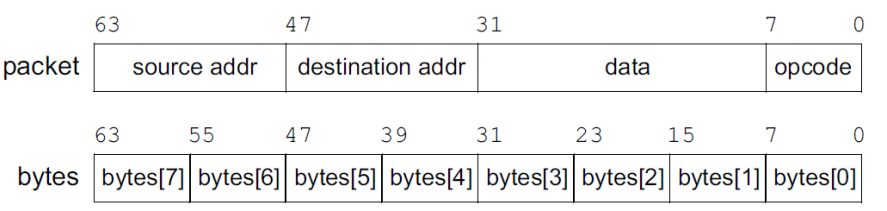
Verilog had only one type of array meanwhile SystemVerilog arrays can be either packed or unpacked.
A packed array is treated as both an array and a single value, the packed dimensions are specified before the variable name
and increase horizontal size (describe columns). E.g. bit [3:0][7:0] mybytes; is a packed array that is stored as a contiguous set of bits
Packed arrays can be made of only the single bit data types (bit, logic, reg)
An unpacked array is treated only as an array and it is stored as an independent set of bits, the unpacked dimensions are
specified after the variable name and increase vertical size (describe rows). E.g. bit mybytes [7:0][3:0]; is an unpacked array that is stored as an independent set of bits
Unpacked arrays can be made of any data type (byte, int, real, bit, logic, etc.)
Packed and unpacked arrays can be mixed. E.g. bit [3:0][7:0] barray [2:0] // 3 elements of 4 8-bit elements (in other words each of the 3 elements is packed into 32 bits)
Arrays & Vectors
Vector:
It is a one-dimensional packed array
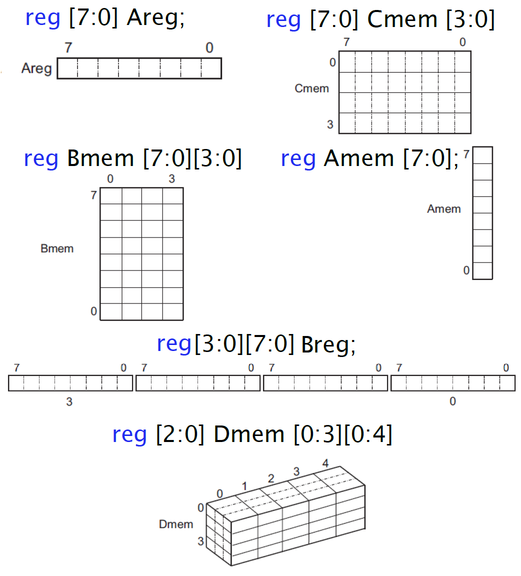
Declaration: reg [7:0] aReg;
You can access individual bits or sections of bits: reg [2:0] sub_vector; assign sub_vector = aReg[5:3];
Array:
reg aMem [7:0];
reg bMem [7:0][3:0];
reg [7:0] cMem [3:0];
SystemVerilog Functions
Functions in SystemVerilog are defined inside the module where they will be used
Functions cannot use delays (E.g. #4) nor posedge or negedge statements
They can have any number of inputs but only one output
They can call other functions but cannot call a task
They cannot use continuous assignments (assign)
Usually used to implement combinational logic that repeats a lot in a module or to do some calculation used to parametrize the module
It can be declared using C style syntax or module style
// C Style function declaration
function integer DoubleWordLength(input integer Word);
    begin
        DoubleWordLength = 2*Word;
    end
endfunction
// Module Style function declaration
function integer DoubleWordLength();
input integer Word;
begin
DoubleWordLength = 2*Word;
end
endfunction
SystemVerilog initial & task
initial
The initial statement
It is a procedural statement / procedural block
It runs once and stops when it reaches its last statement
All initial blocks in a module start at time 0 and run concurrently
it is a non-synthetized block (It cannot be synthetized)
It can be considered as an execution threat typically used to initialize input signals and to launch threads.}
Used along repeat (to repeat an statement N times) and forever (to repeat an statement until simulation ends)
  // initial with delays
  initial
begin
  #31 rst = 1;
  #23 rst = 0;
  rst = #31 1;
  rst = #23 0;
end
  // initial with repeat
  initial repeat (44) #7 enable = ~enable;
  // initial with forever
  initial
begin
  clk = 1'b0;
  forever #2 clk = !clk;
end
Tasks
Tasks can contain delay statements
They can have any number of inputs and outputs
Variables declared in a task are local variables to the task
They can use any global variables declared in a design.
A task can call another task and/or function(s)
A task can be synthetized into combinational or sequential logic but are most commonly used to describe non-synthesizable logic in simulation
Storage for an automatic task or function is effectively allocated each time it is called.
initial Task_Clk;
task Task_Clk;
  begin
    clk = 1'b1;
    forever #1 clk = !clk;
  end
endtask
fork...join
Block that allows parallel execution in a procedural block
Generally used to launch tasks in parallel
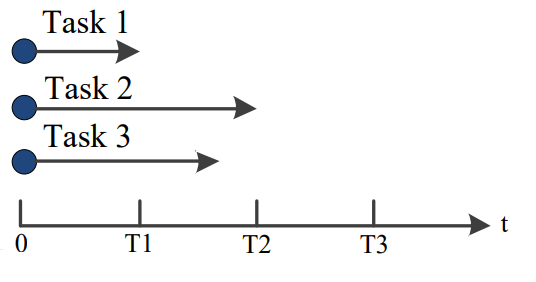
initial begin
  fork
    // All tasks start executing simultaneously
    Task1;
    Task2;
    Task3;
  join
end
// fork...join equivalent to separate initial statements
//initial Task1; initial Task2; initial Task2;
task Task1;
  forever #1 A = !A;
endtask
task Task2;
  forever #2 B = !B;
endtask
task Task2;
  forever #4 C = !C;
endtask
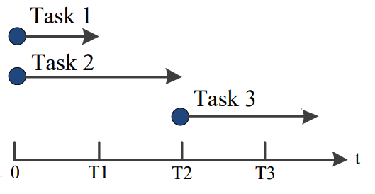
fork...join block schedules each statement in the block but blocks execution in parent thread
initial begin
  fork
    // Task3 starts until Task1 and Task2 completes
    Task1;
    Task2;
  join
    Task3;
end
task Task1;
  repeat (8) #1 A = !A;
endtask
task Task2;
  repeat (16) #1 B = !B;
endtask
task Task3;
  repeat (4) #1 C = !C;
endtask
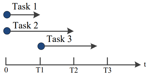
fork...join_any
Schedules each statement in the block just like a regular fork...join block, then when the first statement completes, execution continues in the parent thread
Used to launch a task only after another task finishes
initial begin
  fork
    // Task 1 and 2 start at the same time,
    // when Task1 finishes Task3 starts
    TasK1;
    TasK2;
  join_any
  TasK3
end
task Task1;
  repeat (8) #1 A = !A;
endtask
task Task2;
  repeat (16) #1 B = !B;
endtask
task Task3;
  repeat (4) #1 C = !C;
endtask
fork...join_none
Schedules each statement in the block just like a regular fork...join block, but doesn't block execution in the parent thread, in other words execution continues normally in the parent thread
initial begin
  fork
    // All tasks start executing simultaneously
    TasK1;
    TasK2;
  join_none
  TasK3
end
task Task1;
  repeat (8) #1 A = !A;
endtask
task Task2;
  repeat (16) #1 B = !B;
endtask
task Task3;
  repeat (4) #1 C = !C;
endtask
Interfaces
SystemVerilog Interfaces offers a new paradigm for modeling ports and interconnections, they are an abstraction of an interconnection between modules
Interfaces help us to model communication buses and interconnection in general
They avoid duplication of port declarations in multiple modules and avoid changes in multiple modules if a change in the port is required
Allows signals to be grouped together and represented as a single port. Each module that uses this group of signals has as single port of the interface type instead of many port definitions
With the use of Interfaces common signals are encapsulated into a single location, this eliminates the need of redundant declarations in other modules and simplify connections between modules.
An Interface can contain type declarations, tasks, functions, procedural blocks, program blocks and assertions
Interfaces cannot contain a design hierarchy (this means instances of other modules)
Interfaces can have external signals coming into the interface and can these signals can now be connected to other modules through the interface without explicitly connecting the signals to each module
.* syntax indicates that all ports, nets and variables of the same name in the module should automatically be connected together
modport
SystemVerilog allows multiple views of the interface, this means it allows us to declare the signals in a way that the signal
can be seen as an input, output or inout depending on how the interface is used. For this we use modports
modport allows each module connected to the interface to see the interface, or some of the signals contained in the interface, differently.
E.g. imagine a simple control unit that enables a counter module through an enable signal, the control unit will need to see the enable signal as an output but the counter needs to see it as an input
The modport definitions only defines whether the connecting module sees a signal as an input, output or inout, modport declaration do not contain vector sizes or types, this information must be defined as part of the signal type declarations in the interface
Signals in a module from an interface can be used inside a module as a normal signal using the syntax <interface_name>.<signal_name> or <interface_name>.<modport_name>.<signal_name>
for and generate are used to describe hardware that has a structure with a well define regularity.
generate
It is used to make regular instantiation of modules using sentences like for, if, case
Create multiple instantiation of modules that are connected following a pattern (usually described with a for loop)
It needs a genvar type to iterate
for
It needs to iterate using a reg or integer
Used to describe HW with a regular structure (E.g. a mux implemented with AND and OR gates is just gates connected in a regular structure)
Type definitions - typedef
Using the typedef keyword SystemVerilog adds the ability for the user to define new net and variable types. E.g. typedef logic [7:0] uint_t; uint_t a;
Depending on the context typedef data can be synthesizable
Structures - struct
A structure is a collection of variables and/or constants under a single name
Structures are synthesizable depending on the context
In order to initialize a structure, SystemVerilog uses the tokens '{ }
We can declare a struct type using typedef struct { ... } MyStruct_t;and then create an instance or create a define and create instance just using struct { ... } mystruct;
By default, a structure is unpacked which mean means the members of the structure are treated as
independent variables or constants that are grouped together under a common name. However it can be explicitly
declared as packed in order to store all the members of the structure as contiguous bits in a specified order
A union is similar to a struct, it is also a collection of variables and/or constants under a single name
but the amount of reserved space is dictated only by the largest variable in the union
By default, a union is unpacked which means all its members are represented as contiguous bits but they can also be declared
as packed as long as the number of bits in all the union members is the same
Unpacked unions are not synthesizable and packed unions can be synthesizable depending on the context and also depending on the synthesis tools
Module and interfaces use the scope resolution operator :: and import to include a package definitions, they can import all or just certain definitions
import all contents: import definitions::*;
import specific definitions: import definitions:: Word_Length;
Verilog and System Verilog Modules
Adder
A full adder is a 3-bit adder, it takes the two input bits and the carry from the previous bit.
A half adder takes two bits in and produces two output bits, a sum and a carry:
Mux and Demux
The Multiplexer and Demultiplexer are used to control the flow of data in a design
Multiplexer (Mux)
Demultiplexer (Demux)
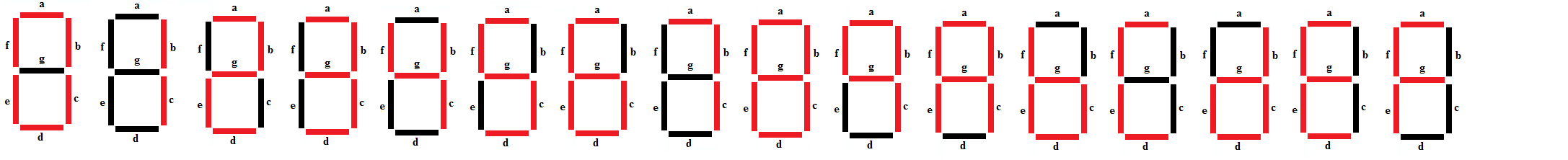
Decoders
BCD to 7-segments display
8-bits Binary to BCD
ALU
Register & Flip-Flop
Flip-Flop is the basic element of memory
Flip flops make sure different processing times (propagation delays) don't cause glitches in outputs.
For synchronous logic. the clock rate needs to be at least twice as fast as the fastest input you need to process.
With synchronous logic the design only "look" at the signals (and store them in a flip flop) on a clock edge
(usually, just the rising edge). Now the circuit will work fine if the longest delay from one flip flop’s output
to the next flip flop’s input is less than the period of the clock.
Clock must be longer that the longest combinational path to avoid glitches. Timing and path delays causes glitches
problem is what happens when your delays are not very tiny but are, instead, very large. If the delay is 1ms, your clock would have to be less than 1 kHz (1/1kHz=1ms)!
Inputs to the flip flop must be stable for the setup time before the active clock edge. The inputs also have to stay stable for at least the hold time, in other words
the signal into the flip flop has to be stable a little bit before the clock edge (set up time) and a little bit after the clock edge (hold time)
If you violate the setup or hold times, the flip flop may go metastable. What this means is the flip flop may behave badly. In some cases it will oscillate or it may take longer to change states than normal.
Most common flip flop implementations
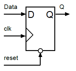
FF with synchronous reset
FF with asynchronous reset
Register
Register with Sync Reset & Enable
Counters
Counter with Flag, Sync Reset and Enable
Ascending-Descending Counter
Clock Divider Counter
PWM with Comparator
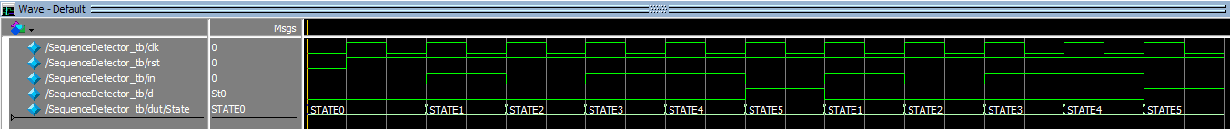
State-Machines
A state machine is one of the strategies used to control a digital system, the control unit of a digital system usually can be implemented with a state machine
Usually implemented in two parts
Sequential part (State assignment)
Combinational part (Outputs assignments)
State machines types
Moore: outputs only depend of the current state so the outputs are fully in sync with the clock
Mealy: Outputs depend of the current state and the inputs so the outputs are not fully in sync with the clock (if the inputs are not in sync with the clock)
In SystemVerilog we can be descriptive and define the state variable as an enum type. E.g. Enum logic {Waiting_State, Multiplying, Close_Channels} state;
EDIF (Electronic Design Interchange Format) If you buy IP (intellectual property) from a vendor, it will probably come as an EDIF file. That means you won't be able to easily edit it, but you can add into your designs.
FPGAs usually have a speed rating and the tools have great models of how long a signal will take to propagate from point A to point B at a certain temperature.
Simulate/test/debug system behavior: don't take into account timing High-fidelity simulate/test/debug on actual device-specific configuration takes into account timing
POF (Programmable Object File) File used to download a design to an FPGA
testbench environment to test a logic design
usually have a reg for each input we want to feed the device under test and a wire for each output